
Subscribe to Our Youtube Channel
Related Manuals for SMITH SYSTEM 58000


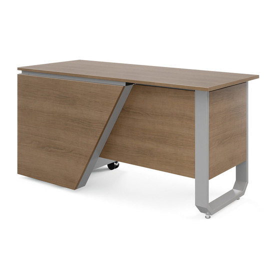
Summary of Contents for SMITH SYSTEM 58000
- Page 1 Assembly Instructions MOTUM TEACHERS DESK FIXED HEIGHT RIGHT HAND MODEL NUMBERS 58000, 58002, 58004, AND 58006 If you have damaged or missing components, please contact customer service at 1-800-328-1061 REVISED: 2/2022 Document #: 179716...
- Page 2 Hardware and Components ITEM NO. DESCRIPTION ITEM NO. DESCRIPTION TEACHER DESK U TUBE LEG ASSEMBLY TD U TUBE LEG Z BRACKET SWIVEL GLIDE W/ GLIDE STOP TD L BRACKET FRONT 120 TEACHER DESK STRAIGHT TUBE LEG ASSEMBLY TD FILLER BRACKET TD BRACED L BRACKET TD L BRACKET FRONT MAIN TD STRAIGHT TUBE LEG Z BRACKET...
- Page 3 13-2 NO. 10 X 1/2" TORX SELF DRILLING BUTTON HEAD SCREW 13-3 10-32 X 1/2" TORX BUTTON HEAD W/PATCH T25 TORX POWER BIT #2 13-4 USED ON USED ON 58002 and 58006 58000 and 58004 REVISED: 2/2022 Document #: 179716...
- Page 4 Hardware and Components BOX B ITEM #B-11 (60140) – TD SPLIT HEIGHT HARDWARE PACK COMPONENTS REVISED: 2/2022 Document #: 179716...
- Page 5 Hardware and Components FOR 60” MODELS ONLY 58000 AND 58002 FOR 72” MODELS ONLY 58004 AND 58006 Document #: 179716 REVISED: 11/2020...
-
Page 6: General Assembly Guidelines
General Assembly Guidelines Special Notes: • Ensure that all components are accounted for and undamaged before assembling • Follow each step carefully to ensure the proper assembly of this product • 2-person assembly is highly recommended • Clean the product with a mild cleaner and damp cloth Tools: •... - Page 7 Assembly Instructions 1. Place wood top on clean smooth surface upside down with the pilot holes facing up, fasten 2x item #7 to item A using 4x fasteners item #1 using the supplied T25 Torx bit item # 4. 2. Position Panel B as shown, centering the panel to create equal gaps, a spacer or credit card works well.
- Page 8 Assembly Instructions 3. Place wood top on clean smooth surface upside down with the pilot holes and reference lines facing up. The reference lines will be used to help align the metal components in future steps, these are only guides final locations will vary by assembly accuracy. (Panel I is used in these instruction, substitute panel I with panel E for 60”...
- Page 9 Assembly Instructions 5. Slide the previously assembled panel A onto item #3, item #7 should side over the metal lip of item #3 as shown. Do not install any fasteners at this point this board will be removed later. It it helpful to clamp panel A to item #3. 6.
- Page 10 Assembly Instructions 7. Align item #11’s edge with the reference line as shown. Item #11 should be touching Item #3 and the faces indicated below should be flush. Fasten #11 to top using 4x fastener #1. Reference line These faces Flush with #11’s edge should be flush 8.
- Page 11 Assembly Instructions 9. Align item #10’s edge with the reference line as shown. Item #10 should be touching Item #11. Fasten #10 to top using 2x fastener #1. These faces of item #10 and #11 should touch Reference line Flush with #10’s edge 10.
- Page 12 Assembly Instructions 11. Align item #9’s edge with the reference line as shown. Item #10 can be used as a spacer for panel G. Insert panel G into the slot of Item #12. Place item #9 against panel G as show. Confirm that all 3x holes on item #12 and item #9 can be seen though the slots while item #10 is in place.
- Page 13 Align edge of tube from item #1 with the edge of the wood(brown surface), NOT the face of the edge banding. 14-A. This step is for 58000 and 58004 only, all other models skip to step 14-B. Remove all components from inside 19179 before inverting. Remove panel A assembly and set to the side.
- Page 14 Assembly Instructions 14-B. This step is for 58003 and 58007 only. Remove all components from inside 19178 before inverting. Remove panel A assembly and set to the side. Position 19178 front face is flush with the edge of wood as shown below, allow for a small gap between the tube of item #3 and hinge.
- Page 15 Assembly Instructions 16. Replace panel A, item #10 can be used as a spacer. Confirm that panel A and F are flush, a framing square is recommended. Install 3x fastener #1 into panel A 17. Place item #14 between the bottom of 19179/19178 and the casters that came with 19179/19178. Install the 16x fasteners that came with 19179/19178.
- Page 16 #15 into panel I. Reference line 18-B. This step is for 60” Models only (58000 and 58002). The indicated face of item #10 should be flush with item #1 as shown. Install 2x fasteners #1 into panel E.
- Page 17 Assembly Instructions 19. Unlock all casters, on a soft, clean surface flip the desk on its front face as shown. Reference line 20. Flip desk onto casters as shown. Document #: 179716 REVISED: 11/2021...
Need help?
Do you have a question about the 58000 and is the answer not in the manual?
Questions and answers