
Related Manuals for SMITH SYSTEM 58020


Summary of Contents for SMITH SYSTEM 58020
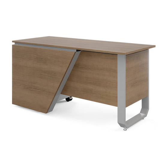
- Page 1 Assembly Instructions MOTUM TEACHERS DESK SPLIT HEIGHT RIGHT HAND MODEL NUMBERS 58020 AND 58022 If you have damaged or missing components, please contact customer service at 1-800-328-1061 REVISED: 2/2022 Document #: 179718...
- Page 2 Hardware and Components BOX A (60149) ITEM NO. DESCRIPTION ITEM NO. DESCRIPTION TEACHER DESK U TUBE LEG ASSEMBLY TD U TUBE LEG Z BRACKET SWIVEL GLIDE W/ GLIDE STOP TD L BRACKET FRONT 120 TEACHER DESK STRAIGHT TUBE LEG ASSEMBLY A-10 TD FILLER BRACKET TD BRACED L BRACKET...
- Page 3 Hardware and Components BOX B (60150) ITEM NO. DESCRIPTION TD SPLIT LAMINATE COVER RH SIDE TD SPLIT LAMINATE COVER RH FRONT SIT-STAND DESK FLIP TOP COLUMN REVISED: 2/2022 Document #: 179718...
- Page 4 Hardware and Components BOX A ITEM #A-13 (60139) – TEACHERS DESK HARDWARE PACK COMPONENTS BOX B ITEM #B-11 (60140) – TD SPLIT HEIGHT HARDWARE PACK COMPONENTS REVISED: 2/2022 Document #: 179718...
- Page 5 Hardware and Components FOR 60” MODEL ONLY FOR 72” MODEL ONLY 58020 58022 REVISED: 2/2022 Document #: 179718...
-
Page 6: General Assembly Guidelines
General Assembly Guidelines Special Notes: • Ensure that all components are accounted for and undamaged before assembling • Follow each step carefully to ensure the proper assembly of this product • 2-person assembly is highly recommended • Clean the product with a mild cleaner and damp cloth Tools: •... - Page 7 Assembly Instructions 1. Place wood top on clean smooth surface upside down with the pilot holes facing up, fasten 2x item #A-7 to item A using 4x fasteners item #13-1 using the supplied T25 Torx bit item #13-4. 2. Slide the previously assembled panel A onto item #A-3, item #A-7 should side over the metal lip of item #A-3 as shown.
- Page 8 Assembly Instructions 3. Using previously assembled components install item #A-4 and #A-5 using 4x fastener #13-3, do not fully tighten, install item #B-2 using 3x fastener #13-1 note to orientation of #B-2, do not fully tighten. Optional: Use 1x fastener #13-1 to hold #A-3 in place.
- Page 9 Assembly Instructions 5. Fasten 4x item #B-8 and 1x item #B-9 to panel P using 10x fasteners item #11-1 using the supplied T25 Torx bit item #13-4. These faces should be flush 6. Position Panel S as shown over the top of item #B-12. Fasten panel S to item #B-12 using 4x fasteners item #11-3 and #11-10, finger tighten only.
- Page 10 Assembly Instructions 7. Using 2x item #A-10 as spacers. Place panel F as shown. Confirm edges of panels F and A align as shown. Fasten panel F with the 2x indicated fastener #13-1. Confirm edges of panels F and A are still aligned before installing the remaining 6x #13-1 fasteners 8.
- Page 11 Assembly Instructions 9. Fasten item #B-7 with 6x fastener #11-1, it is recommended to use a square to ensure panel P is vertical. 10. Remove noted fastener from step 3. Install item #B-1 as shown using 6x fastener 11- 1 and 3x fastener 11-3. REVISED: 2/2022 Document #: 179718...
- Page 12 Assembly Instructions 11. Slide item #B-4 under item #A-11. Align the edges of item #A-11 and #B-8 with the reference line as shown. Fasten down using 6x fastener #11-1 Reference Line Align the edges of items #B-8 and #A-11 with the reference lines 12.
- Page 13 Assembly Instructions 13. Place item #A-12 as shown. Confirm faces of panel F and item #A-12 align as shown. Fasten item #A-12 with the 5x fasteners #11-1. Edges of panel F and item #12 should be flush as shown, check top and bottom before fastening.
- Page 14 Assembly Instructions 15. Place the previously assembled item #A-1 and panel B as shown. Attach item #A-8 using 2x fastener #13-1 to panel G and attached item #A-8 to item #A-1 using 2x fastener #13-3, finger tighten only. Confirm the gap between item #A-1 and panel G is constant and as minimal as possible as shown below.
- Page 15 Assembly Instructions 17-A. This step is 72” model only (58022), for 60” model (58020) skip to step 17-B. Line up item #5 with the reference line. Install 8x fasteners #6 from hardware pack supplied with item #5 into panel U.
- Page 16 Assembly Instructions 18. Place item #B-10 with the tape face down. Position item #11 as shown below, fasten to item #B-10 using 4x fasteners #11-5 and #11-11 Cable should face the same side as the wider side of item #B-10 19.
- Page 17 Assembly Instructions 20. On a soft, clean surface flip the desk on its front face as shown. Insert the previously assembled panel R into the unit as shown, fasten panel R with 2x fastener #13-1. Panel R should be on this side of the metal flange 21.
- Page 18 Assembly Instructions 22. Install item #B-6 first as shown below by sliding the tab into the slot of item #A-11. Slide over to lock into place. Repeat step for item #B-3. Slide item #B-6 back to touch item #B-3. These faces should be flush 23.
- Page 19 Assembly Instructions 24. Install item #7, #8, #9 and #10 as shown below. Caster with lock (#8) on top side 25. Carefully flip table to stand upright, without removing the tape backing, place panel K on top of item #B-10. While pressing the right lever, push down on panel K until it makes contact with the top of item #B-3.
- Page 20 Assembly Instructions 26. While applying pressure to panel K, press right lever to raise lift mechanism fully. Using 4x fastener #13-1, attach top K as shown while applying pressure from above. 27. Attach lift the lever and item #11-6 with 4x fastener #13-1 choosing your left- or right- hand operation.
- Page 21 Assembly Instructions 28. Assemble door lock item #B-5 as shown with the gray laminate side facing up. Install item #2 using 2x fastener #3. Hammer in this metal orientation before installing lock. 29. Place previously assembled panel Q as shown, installing indicated 3x fastener #13-1 first. Confirm the door hangs level, latches, and locks correctly.
Need help?
Do you have a question about the 58020 and is the answer not in the manual?
Questions and answers