
Related Manuals for SMITH SYSTEM Flowform 56201


Summary of Contents for SMITH SYSTEM Flowform 56201
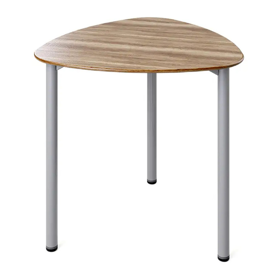
- Page 1 Assembly Instructions Flowform Outdoor Tables If you have damaged or missing components, please contact customer service at 1-800-328-1061 Document #: 179699 REVISED: 7/2022...
- Page 2 Hardware and Components (PN: 78978 OUT) FLOWFORM OUTDOOR TOP (PN: 78532 SHOWN PN: 78533 PN: 78534 PN: 78537 PN: 78538) QTY. 1 48” STIFFENER BAR FOR 56213 MODEL ONLY (PN: 72157) QTY. 1 OUTDOOR LEG MODELS 56201, 56203 QTY. 3 MODELS 56213, 56214, 56215 QTY.
-
Page 3: Special Notes
Special Notes: • TOOLS REQUIRED: • Drill with T25 Torx power bit (bit provided), or T25 Torx head screwdriver. • Drill with 5/16” Socket • 3/16” Allen Wrench (provided) • Check that all components are accounted for and undamaged before assembling. •... - Page 4 Assembly Instructions 1. Place wood top on clean smooth surface upside down with the pilot holes facing up. Top may be heavy; team lifting is encouraged. 2. FOR MODEL 56213 ONLY: Place 48” Stiffener Bar on top lining up with the pilot holes in the center as shown.
- Page 5 3. FOR ALL MODELS: Place Outdoor Leg on top lining up with the pilot holes as shown. Using the T25 Torx Power Bit, install 10 of the #10-14 x .425” Tri-Lobe Trespa Screws to secure the leg to the top. 4.
- Page 6 6. STEP A: Remove preinstalled leveling glide. STEP B: Install the Anchor Bracket using the supplied 3/8-16 X 1” fastener using the 3/16” Allen wrench. STEP C: 1/2” from the edge of the metal leg tube, install the #10 X 5/8” self-drilling screw using a 5/16”...
-
Page 7: Replacement Hardware
Replacement Hardware [REPLACEMENT HARDWARE PACK: 60132-R] [REPLACEMENT HARDWARE PACK: 60134-R} #10-14 X .425” TRI-LOBE #10-14 X .425” TRI-LOBE TRESPA SCREW TRESPA SCREW QTY. 14 QTY. 10 [REPLACEMENT HARDWARE PACK: 78980-R] #10 X 5/8” SELF-DRILLING 3/8-16 X 1” FLAT HEAD SCREW WITH RUBBER MACHINE SCREW WASHER QTY.
Need help?
Do you have a question about the Flowform 56201 and is the answer not in the manual?
Questions and answers