
Related Manuals for SMITH SYSTEM Lift Desk


Summary of Contents for SMITH SYSTEM Lift Desk
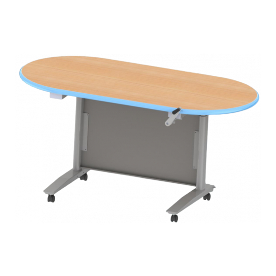
- Page 1 Lift Desk Assembly Instructions For Assistance in assembling product, missing or damaged parts, or to place an order, please contact customer service at 800-328-1061 You may also place your order online at www.smithsystem.com Form# 179963 09/2013...
- Page 2 Hardware and Components Lift Desk Hardware Pack Small Modesty Panel QTY: 1 Large Modesty Panel QTY: 1 QTY: 1 Crankshaft Rod Top Support Brace Bottom Support Brace QTY: 1 QTY: 1 QTY: 1 Replacement Fastener Hardware Pack 17708 – Crank Desk Fasteners: 1.
- Page 3 Step 1: Flip the top over so the laminate is face down. Step 2: Using the crank shaft rod, manually lower each of the legs to the bottom separately by inserting the crankshaft rod around the knobs one at a time. Insert the rod on the left and twist the rod clockwise until bottomed out.
- Page 4 Step 4: Using (4) of the ¼-20 screws, attach the top brace to the legs. Make sure that the large holes on the brace are facing away from the table top. Step 5: Attach the large panel to the top brace using (3) ¼-20 screws. Make sure that all flanges are facing towards the front of the table.
- Page 5 Step 6: Remove the Hex bolt from inside the crank handle rod. Place the Crank Handle on the Crank Handle Rod. Refasten the Hex bolt into the crank handle rod. Step 7: Crank the desk all the way extended. For Assistance in assembling product, missing or damaged parts, or to place an order, please contact customer service at 800-328-1061 You may also place your order online at www.smithsystem.com...
- Page 6 Step 8: Using (4) ¼-20 screws, attach the Small Modesty Panel onto the Legs (2 people are recommended for this step). Be sure that the large modesty panel slides into the small modesty slots behind the small modesty panel. The side flanges on the small modesty panel should face towards the back of the table, while the flanges on the top and bottom of the small modesty panel should face towards the front.
- Page 7 Step 10: Crank the desk up and down a few time to ensure the gears operate correctly. Step 11: Using (7) wood screws for the 30” and (9) wood screws for the 60”; attach the frame to the table top. (The extra (2) wood screws on the 60” go on the top support brace). For Assistance in assembling product, missing or damaged parts, or to place an order, please contact customer service at 800-328-1061 You may also place your order online at...
- Page 8 Step 12 (Optional): If desired, attach the (4) casters onto the feet using (16) M5X10mm screws. The locking casters are most helpful in the front caster position, while the 2 non-locking in the rear caster positions. Step 12 (Optional): If desired, attach the (4) glides onto the feet. For Assistance in assembling product, missing or damaged parts, or to place an order, please contact customer service at 800-328-1061 You may also place your order online at...
Need help?
Do you have a question about the Lift Desk and is the answer not in the manual?
Questions and answers