Wavetronix Click 65 Series User Manual
Hide thumbs
Also See for Click 65 Series:
- User manual (49 pages) ,
- Installation & quick start manual (4 pages)
Table of Contents
Advertisement
Advertisement
Table of Contents

Related Manuals for Wavetronix Click 65 Series


Summary of Contents for Wavetronix Click 65 Series
- Page 1 Click 65x Series USER GUIDE...
- Page 2 Click 65x USER GUIDE Springville, Utah 801.734.7200 www.wavetronix.com...
- Page 3 FCC Part 15 Compliance: The Wavetronix SmartSensor sensors comply with Part 15 of the Federal Communications Com- mission (FCC) rules which state that operation is subject to the following two conditions: (1) this device may not cause harmful interference, and (2) this device must accept any interference received, including interference that may cause undesirable operation.
-
Page 4: Table Of Contents
CONTENTS Introduction Using this guide QUICK START GUIDE Installing the Click 65x Configuring using the front panel Configuring the sensor Configuring using the web interface Using the PROPERTIES tab Using the SENSORS tab Using the CHANNELS tab Using the VERIFICATION tab Using the HEALTH tab HARDWARE AND INSTALLATION DETAILS Making connections... - Page 5 Channels tab Adding multiple sensor channels Using the MMU tab Copying and pasting BIUs Verification tab Health tab Graphs tab Data Summary Count Details Arrival Profile Other functions Export/Import configuration Upgrade page Admin page SDLC TS1/TS2 controllers TS2 controllers and Click 65x devices...
-
Page 6: Introduction
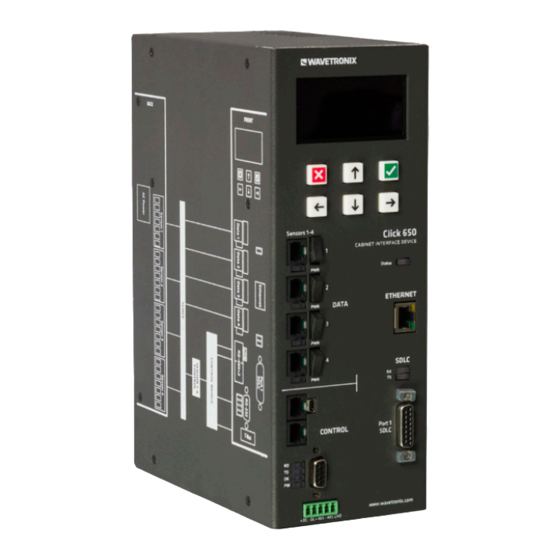
(Click 650) or six (Click 656) SmartSensor Matrix or Advance sensors. They are designed to serve as replacements for the Wavetronix full and segmented backplates, providing the same functionality with a smaller cabinet footprint. Figure 1. The Click 650 (left) and 656 (right) -
Page 7: Using This Guide
They also provide an Ethernet port for direct connection to local networks. You can access the serial-based sensors using Wavetronix SmartSensor Manager software over TCP/IP using a network-connected laptop, tablet, or workstation. The devices also contain the same contact closure outputs and... -
Page 8: Quick Start Guide
Quick Start Guide There are four main steps for installing and using the Click 65x: Installation Front panel configuration Sensor configuration Web configuration Installing the Click 65x Place the Click 65x in the traffic cabinet. They are designed to Note. There is a 19-inch rack shelf be shelf-mounted, but can also be mounted to the cabinet wall option available... -
Page 9: Configuring Using The Front Panel
Configuring using the front panel Select Network Setup from the main menu using the keypad. Enter an IP address, subnet mask, and default gateway for the local network. Make note of the IP address for further configura- tion later. If desired, select Utilities >> Display Off to set the amount of inactivity on the main OLED panel display before it shuts off. - Page 10 Advance – For Advance and Advance Extended Range sen- ̀ sors, connect using the Internet tab with the IP address of the Click 65x unit, default port 10001. Select the Multi-drop Network tab with Automatically Detect Sensors checked. Figure 3. SmartSensor Manager Advance Use SmartSensor Manager to configure and validate each sensor.
-
Page 11: Configuring Using The Web Interface
Configuring using the web interface Open a web browser on the connected laptop or tablet. Type the Click 65x IP address into the browser's URL field. The Click 65x web interface should load. Figure 4. Click 65x web interface Using the PROPERTIES tab Select the PROPERTIES tab at the top of the screen and enter Note. -
Page 12: Using The Channels Tab
previous instance of SmartSensor Manager is currently con- nected to the sensor. Using the CHANNELS tab Select the CHANNELS tab at the top of the screen. Each enabled BIU number will have 16 available detector channels. For each desired detector channel to transmit to the controller, select a sensor and sensor channel using the drop- down lists. -
Page 13: Hardware And Installation Details
Hardware and Installation Details The Click 650 and 656 are shelf-mount devices, intended to be set on a shelf in the traffic cabinet. They can also be attached to the wall of a NEMA-style cabinet using U-channel mounting brack- ets, or placed on a 19-inch rack shelf; both are available in separate accessory packages. - Page 14 OLED Panel FRONT & Keypad www.wavetronix.com DATA Click 656 CONTROL Data Bus RS-485 Connectors, Ethernet Port Serial Ethernet Port 1 SDLC Status SDLC T-bus 5-position Control Bus RS-485 Connectors, Connector USB Connectors, SDLC LED Indicators, Port 1 SDLC, RS-232 Connector and LED Indicators Figure 5.
-
Page 15: Making Connections
One DB-9 port for communicating via RS-232 ̀ Two RJ-11 jacks for communicating via RS-485 ̀ One USB mini-B connector ̀ One T-bus port for connecting to a T-bus ̀ This section also has the following LEDs that will be helpful to monitor the status of the Click 65x device. -
Page 16: Terminating The Smartsensor 6-Conductor Cable
Surge protection You don’t need to do anything to get the surge protection running; just be aware that this device provides protection for the cabinet from surges coming in on the sensor cables. (SmartSensor devices have their own onboard surge protection.) Terminating the SmartSensor 6-conductor cable Each Click 650 can interface with up to four sensors;... -
Page 17: Connecting Data To The Traffic Controller
according to the color code shown below. Make sure the wires are completely inserted in the terminal. Close the insulation displacement connector by reinserting the Note. Do not strip the service end of screwdriver into the square slot and rocking it forward. The the cable until after plug-in terminals will automatically complete the electrical con- it has been routed... -
Page 18: Using The Control Bus To Configure The Sensors
each jack is an LED that illuminates when the associated sensor has power. (The power switch and LED light apply to the desig- nated sensor, whether or not the associated RJ-11 jack is being utilized for contact closure connections.) Using the control bus to configure the sensors The lower portion of the front faceplate has multiple ports that make up the physical interface of the control bus. -
Page 19: Oled Panel
OLED Panel The Click 650 and 656 have two primary interfaces for user access and configuration: The OLED panel and keypad, used for basic and preliminary ˿ configuration (discussed in this chapter). The web interface, accessed through any web browser from ˿... - Page 20 Figure 7. OLED panel The screen brightness of the OLED panel can be adjusted by hold- ing down the left arrow button and pushing the up or down arrows to raise or lower the screen brightness, respectively. Figure 8. OLED panel menu The main OLED panel menu contains the following menu options: Device Info –...
-
Page 21: Device Info
current detector mappings and signals for verification purposes. Utilities – Other miscellaneous settings for the Click 65x ˿ device. Device Info Figure 9. Device Info The Device Info screen contains a read-only display of important Note. These fields are not directly configuration and description information. -
Page 22: Network Setup
Network Setup Figure 10. Network Setup The Network Setup screen contains three fields that are editable through the OLED front panel. Follow the steps below to change the information in the fields: For each field, use the left and right arrow keys to move between each number. -
Page 23: Biu Setup
check) button to save the network configuration. Push the Cancel (red X) button to return to the main menu without saving. The fields that can be edited on this screen are as follows: IP Address – Displays the IP address assigned to this device ˿... -
Page 24: Verify Output
Interface Unit) to be activated or deactivated. Each BIU ID has six- teen available detector channels, and deactivating a BIU number will disable the use of that set of channels. Follow the steps below to activate or deactivate the BIUs: Use the up and down arrows to move between the options and and push the right arrow button to toggle the BIU activation. -
Page 25: Utilities
Utilities Figure 13. Utility Menu The Utility screen has three options. The Control Port setting allows the control ports on the front side of the device to be in Lim- ited or Dedicated mode. Limited – This is the default setting for normal activity. ˿... -
Page 26: Web Interface
Web Interface The Click 65x web interface is the primary mechanism for access- Note. Before connecting to the ing Click 65x functionality. The web interface provides many web interface, options that cannot be accessed using the front panel OLED. connect the Click 65x to the local network The web interface can be accessed by typing the device IP and set its network... -
Page 27: Properties Tab
Properties tab Figure 16. Properties tab The Properties tab contains basic configuration information about the Click 65x device, with the ability to edit many of those fields directly from this screen. Serial Number – The registered serial number for this device. ˿... -
Page 28: Sensors Tab
Enable Sensor Data Port – These checkboxes activate or ˿ Note. Since the web interface URL deactivate the respective sensor port for communication. Ports uses the device IP with a sensor attached need to be activated before sensor address, if the IP events will be transmitted by the Click 65x. -
Page 29: Channels Tab
Make sure the devices are discovered; each device will be Note. The Location, Description, and listed in their own identification box in the Available Sensors Approach fields section. Sensors will be listed as “Sensor X” with X being are taken from the the number of the port to which the sensor is attached. - Page 30 The Click 65x has four available BIUs (9–12) with 16 detector chan- nels available for each. The Detector Channel Map grid shows all 16 available channels for the selected BIU ID. Select a different BIU tab to switch detector channel maps. (Disabled BIU IDs will not be displayed.) Within the Channel Map grid, there are seven individual columns.
-
Page 31: Adding Multiple Sensor Channels
Not all detector channels need to be assigned. To leave a detector channel unassigned, set the Sensor Selection and Sensor Chan- nel columns blank (“---”). Detector channels do not need to be assigned in order—any of the available detector channels can be assigned or left blank depending on your preference. - Page 32 After adding two or more sensors, each sensor will be assigned a unique letter (a, b, c, etc.) in the Logic ID column. Using the Logic: field, create a logical relationship by clicking each sensor button with an and or or button separating them. For example, a detector channel that only triggers when both sensor channel a and b are active would be defined by pushing a, then and, then b.
-
Page 33: Using The Mmu Tab
Using the MMU tab Note. MMU mappings have no functional effect on Click 65x operation and can be safely ignored by the majority of users. The mapping tab is provided as a forward- compatibility feature for future Matrix or Advance firmware containing advanced functionality that depends on correct... -
Page 34: Verification Tab
Verification tab Figure 21. Verification tab The Verification tab allows you to check the current detection mappings using real-time data coming from the sensors. The Chan- nel Verification box contains a 4x4 grid that displays all 16 possible detection channels for the selected BIU. The Verification tab will be updated in real time, so you will see the channel activations trigger on and off as vehicle detections are made by the attached sensors. -
Page 35: Health Tab
Health tab Figure 22. Health tab The Health tab allows you to check current sensor health and status for all attached sensors. This tab will be the default tab seen when you first log into the Click 65x web interface. All sensors discovered and registered to the Click 65x will have an individual listing with its name, location, description, approach and serial number. -
Page 36: Graphs Tab
Graphs tab Figure 24. Graphs tab The Graphs tab can generate tables and graphs for volumes Note. If a phase has not been assigned (counts) and arrival on green data, based on the last thirty-one to a given channel days’ worth of data. in the Channels tab, the AoG will Be aware that for Arrival Profile information to be meaningful, the... -
Page 37: Count Details
data (remember that you can only access data from the last 31 days). Use the Start Time field to choose the time for which you want data. Use the Duration drop-down to choose the period of time you want to view data for. Use the BIU boxes to select which channels you want to show Note. - Page 38 shown in this graph to show the general status and behavior of this intersection. As with the Data Summary tab, use the box on the left to select the Duration of time, Date, and Start Time for which to display the data.
-
Page 39: Arrival Profile
Arrival Profile Figure 26. Arrival Profile tab The Arrival Profile tab generates a bar graph showing the number of vehicles arriving on red vs. those arriving on green, over time. This lets you see how vehicles are arriving in relation to the start of green at this intersection. -
Page 40: Other Functions
The Main link will return you to the main page. The Admin link will be covered in the next section. The About link provides a direct link to the Wavetronix webpage and any other relevant information about the Click 65x device or web interface. -
Page 41: Admin Page
The Upgrade link allows you to upgrade a new Click 65x firmware file to the device. Copy the new firmware file to the local tablet, laptop, or workstation and select Choose File to choose the file in the local file system. Once the file is identified, click Upload File to upload and configure the new firmware on the Click 65x device. - Page 42 Trigger Speed Message Forwarding This section allows trigger speed messages from the SmartSensor Advance to be forwarded to an application that is listening on a UDP port. Please contact support@wavetronix.com for more infor- mation on this feature. Figure 30. Trigger Speed Message Forwarding...
- Page 43 Should you ever lose this password, it can be cleared on the device itself, in the OLED panel menu. You can also contact support@wavetronix.com for assistance. Figure 31. Security Settings Click the Save button after making any adjustments.
- Page 44 Set Date & Time This section shows the current device date and time. If the Click Note. The Click 65x will not start 65x is connected to a traffic controller, it should automatically get collecting SPM data the correct time from that device. until it has a valid date and time.
- Page 45 SDLC SDLC stands for Synchronous Data Link Control protocol. It was developed by IBM in the mid-1970s as part of their Systems Net- work Architecture. While not used commonly in modern computer systems, it is still found among modern traffic controllers. When TS2 controllers were introduced, the specification indicated that cabinet interfaces were to be based on data transmission rather than discrete signals.
-
Page 46: Ts1/Ts2 Controllers
Shelf mount contact closures were also used where racks were not available. Wavetronix sensors can interface to these controllers using either a backplate-to-con- tact-closure connection or by using a Click 600 series cabinet interface device to connect the contact closure outputs. -
Page 47: Ts2 Controllers And Click 65X Devices
BIU. This design works well when four (Click 650) or six (Click 656) Wavetronix sensors are connected through the Click 65x’s SDLC bus utilizing 64 channels of detection. - Page 48 Figure 37. TS2 Type 2 The system operation for TS2 Type 2 when operating like a ˿ TS1 or when used with a TS1 – The controller offers TS1 oper- ating mode with the MMU and/or CMU operating in TS1 mode. Detectors, load switches, flash relays, and flashers also operate in TS1 mode with each connected to the A, B, or C harnesses.
- Page 49 Figure 38. TS2 Type 2 Operating like a TS1 Click 65x User Guide •...
- Page 50 www.wavetronix.com...
Need help?
Do you have a question about the Click 65 Series and is the answer not in the manual?
Questions and answers