ProMinent Makro TZ Operating Instructions Manual
Diaphragm metering pump
Hide thumbs
Also See for Makro TZ:
- Operating instructions manual (88 pages) ,
- General operating instructions (29 pages) ,
- Operating instructions manual (61 pages)
Table of Contents
Advertisement
Quick Links
Operating instructions
Diaphragm metering pump
Makro TZ, TZMb
EN
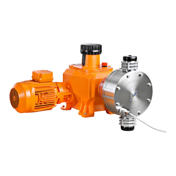
P_MA_0022_SW
Please carefully read these operating instructions before use. · Do not discard.
The operator shall be liable for any damage caused by installation or operating errors.
The latest version of the operating instructions are available on our homepage.
Part No. 985741
Original operating instructions (2006/42/EC)
BA MA 021 01/20 EN
Advertisement
Table of Contents

Related Manuals for ProMinent Makro TZ


Summary of Contents for ProMinent Makro TZ
- Page 1 Operating instructions Diaphragm metering pump Makro TZ, TZMb P_MA_0022_SW Please carefully read these operating instructions before use. · Do not discard. The operator shall be liable for any damage caused by installation or operating errors. The latest version of the operating instructions are available on our homepage.
- Page 2 Supplemental directives Supplementary information Read the following supplementary information in its entirety! Should you already know this information, you will benefit more from referring to the operating instructions. The following are highlighted separately in the document: Enumerated lists Fig. 1: Please read! Operating guidelines ð...
-
Page 3: Table Of Contents
Table of contents Table of contents Identity code................5 Safety chapter............... 7 2.1 Safety information for ATEX designs......14 2.2 Explanation of the ATEX label........24 Storage, transport and unpacking........27 Overview of equipment, control elements......28 Functional description............30 Assembly................ - Page 4 Table of contents Motordatenblatt..............85 Earthing/equipotential bonding drawings for TZMb.... 86 Diagrams for adjusting the capacity........87 Spare parts................. 91 18.1 Spare parts............... 91 18.2 Other material............92 18.2.1 Gear oil..............92 Declaration of Conformity for Machinery......93 Declaration of Incorporation..........94 ATEX Declaration of Conformity.........
-
Page 5: Identity Code
Identity code Identity code TZMb Makro TZ diaphragm metering pump Power end type Main power end Main power end, doubled Add-on power end Add-on power end, doubled Type _ _ _ _ Performance data at maximum back pressure and type: refer to nameplate on the... - Page 6 Identity code TZMb Makro TZ diaphragm metering pump V(0) Variable speed stroke control motor with inte‐ grated frequency converter Speed control complete 3-phase, 230 V/400 V, 50 Hz, (Exe, Exd) 3-phase, 230 V/400 V 60 Hz (Exe, Exd) V(2) Variable speed stroke control motor with inte‐...
-
Page 7: Safety Chapter
Observe the general limitations with regard to viscosity limits, chemical resistance and density - see also the ProMinent Resistance List (in the Product Catalogue or at www.promi‐ nent.com)! All other uses or modifications are prohibited. - Page 8 Safety chapter Only allow trained and authorised personnel to operate the pump - see the following table. Other people may only access the pump if they have been informed about the dangers. You have a responsibility to adhere to the information con‐ tained in the operating instructions at the different phases of the unit's service life.
- Page 9 Trained user A trained user is a person who fulfils the requirements demanded of an instructed person and who has also received additional training specific to the system from ProMinent or another author‐ ised distribution partner. Service Service refers to service technicians, who have received proven training and have been authorised by ProMinent or ProMaqua to work on the system.
- Page 10 Safety chapter Safety information CAUTION! These operating instructions include notes and extracts from German regulations relating to the operator's scope of responsibility. This information does not discharge the operator from his responsi‐ bility as an operator and is intended only to remind him or make him aware of specific problem areas.
- Page 11 Danger of injury to personnel and material damage The pump must only be opened at those points required to be opened by these operating instruc‐ tions. It may only be opened in other positions upon receipt of written authorisation from the ProMinent head office, Heidelberg.
- Page 12 The use of untested third party parts can result in personnel injuries and material damage. – Only fit parts to metering pumps, which have been tested and recommended by ProMinent. CAUTION! Danger from incorrectly operated or inadequately maintained pumps Danger can arise from a poorly accessible pump due to incorrect operation and poor maintenance.
- Page 13 Safety chapter Safety equipment Protective equipment P_MA_0042_SW Fig. 2: Isolating protective equipment for Makro TZ with add-on power end (shown here for plunger design) Motor terminal box cover Protective cowling over the motor fan Flange cover, side Protective cover (diaphragm and plunger design only)
-
Page 14: Safety Information For Atex Designs
Safety chapter Install the motor - with designs without motor Select a suitable motor - it must correspond to the data for one of the motors from the "Motor data" table - see Chapter "Technical data" Fit the motor correctly on the flange (qualified personnel). As you have converted an "incomplete machine"... - Page 15 Safety chapter Task Qualification Maintenance, repair ATEX qualified person, ATEX electrical technician Troubleshooting Qualified ATEX technician or ATEX electrical technician - depending on the fault; Checking the electrical installa‐ tion: Recognised competent person Explanation of the table: Recognised competent person To carry out explosion hazard inspections the competent person must have: completed a relevant course of study or...
- Page 16 Safety chapter Summary of relevant ignition hazards and protective measures put in place for the Makro TZ in accordance with EN ISO 80079-36 Ignition hazard Protective measures to be observed by the cus‐ tomer Excessive surface pressure Limitation of the maximum temperature of the feed...
- Page 17 Safety chapter Ignition hazard Protective measures to be observed by the cus‐ tomer Ignition hazard with bought-in motor components Refer to the documentation for the motor. Comply with the monitoring intervals. The insulation resistance must be greater than 5 MOhm. Provide a time-delay residual current device.
- Page 18 Safety chapter WARNING! ATEX pumps in areas at risk from explosion – A flow control is needed to stop the pump as soon as no flow is detected. WARNING! ATEX pumps and flammable media Only with material versions PP_, PV_ and PC_: The ignition temperature is reduced significantly below the ignition temperature at atmospheric pressure due to compression with the discharge...
- Page 19 Safety chapter WARNING! The following applies in areas at risk from explo‐ sion: – Note the details of the type examination certifi‐ cate PTB 00 ATEX 2048 X for the Namur sensor NJ1.5-8GM-N as well. WARNING! ATEX pumps in areas at risk from explosion –...
- Page 20 Safety chapter WARNING! ATEX pumps in areas at risk from explosion – Carry out a general check to ensure that the system is working properly, particularly the power end and bearings, by regularly moni‐ toring it (for leaks, noises, temperatures, smell, etc.).
- Page 21 If the coupling is OK, the maintenance interval can be increased to 4000 hours. If the coupling is not clearly OK: Call ProMinent Service. After 20,000 operating Adhere to the motor manufacturer's recommendations - see hours or 26,000 operating operating instructions for the motor.
- Page 22 Safety chapter Installation height Data Value Unit Maximum installation height*: 1000 m a.s.l. * We urgently advise you to contact a specialist for ATEX motors with higher intended installation heights! Namur sensor (Specified for EX 5–25 V DC, in accordance with Namur or DIN 19234, potential-free zones) design.
- Page 23 Safety chapter Install the motor - with designs without motor Select a suitable motor - it must correspond to the data for one of the motors from the "Motor data" table - see Chapter "Technical data". WARNING! EX is relevant in areas at risk from explosion! Fit the motor correctly on the flange (qualified personnel).
-
Page 24: Explanation Of The Atex Label
2.2 Explanation of the ATEX label in accordance with Directive 2014/34/EU and standards EN ISO 80079-36, -37 Explanation of the pump’s ATEX labelling Makro TZ Unit group No mines or associated underground systems, which can be endangered by firedamp - Unit... - Page 25 Safety chapter WARNING! Example of EX-designation: Where may I use the ATEX version of the Makro TZ? The pump designation is: " ... II 3G Ex h IIB T4 Gc". The pump label corresponds to “Unit group” II: the pump may only be used in overground production systems, which are not at risk from firedamp.
- Page 26 Safety chapter WARNING! Example 2 - EX-designation: Where may I use the ATEX version of the Makro TZ? The pump designation is " ... II 2G Ex h IIC T4 Gb X". The pump label corresponds to “Unit group” II: the pump may only be used in overground production systems, which are not at risk from firedamp.
-
Page 27: Storage, Transport And Unpacking
Storage, transport and unpacking Storage, transport and unpacking Safety Information WARNING! Only return metering pumps for repair in a cleaned state and with a flushed liquid end - refer to "Decommissioning! Only return metering pumps with a completed Decontamination Declaration form. The Decon‐ tamination Declaration constitutes an integral part of an inspection / repair order. -
Page 28: Overview Of Equipment, Control Elements
Overview of equipment, control elements Overview of equipment, control elements Power end, single head P_MA_0023_SW Fig. 4: Side view (here TZMb H) A Drive C Liquid end Vent screw Stroke length adjustment wheel Oil inspection window Motor Oil drainage screw Power end, double head P_MA_0024_SW Fig. - Page 29 Overview of equipment, control elements Liquid end P_MA_0025_SW Fig. 6: View of the liquid end Discharge valve Dosing head Diaphragm rupture sensor Suction valve Tube nozzle for leakage Protective cover...
-
Page 30: Functional Description
Functional description Functional description Pump The metering pump is an oscillating diaphragm pump, the stroke length of which can be adjusted. An electric motor drives it. -
Page 31: Assembly
Assembly Assembly Refer to the correct dimensional drawings on – our website www.prominent.com for assis‐ tance. Compare the dimensions on the dimensional – drawing with those of the pump. Install the motor - with designs without motor Select a suitable motor - it must correspond to the data for one of the motors from the "Motor data"... - Page 32 Assembly Space requirement WARNING! Motor may overheat If the necessary cooling air supply is not guaran‐ teed, the motor may overheat. In an area at risk from explosion, it could trigger an explosion. – Maintain sufficient clearance between the air intake opening and the walls.
- Page 33 Assembly Fastening Capacity too low Vibrations can disturb the liquid end valves. Secure the metering pump so that no vibra‐ – tions can occur. Take the dimensions (m) for the fastening holes from the appro‐ priate dimensional or data sheets. Use appropriate screws to fix the pump base to the supporting floor.
-
Page 34: Installation
Installation Installation CAUTION! Danger of injury to personnel and material damage Disregarding the technical data during installation can lead to personal injuries or damage to prop‐ erty. – Observe the technical data - refer to the "Tech‐ nical Data" chapter and, where applicable, the operating instructions for the accessories. - Page 35 Installation WARNING! The following measures are an advantage when working with highly aggressive or hazardous feed chemicals: – Install a bleed valve with recirculation in the storage tank. – Install an additional shut-off valve on the dis‐ charge or suction ends. CAUTION! Warning of backflow A back pressure valve or a spring-loaded injection...
- Page 36 Installation CAUTION! Uncontrolled flow of feed chemical Feed chemical can press through the metering pump in an uncontrolled manner in the event of excessive priming pressure on the suction side of the metering pump. – Do not exceed the maximum permissible pri‐ ming pressure for the metering pump or –...
-
Page 37: Basic Installation Notes
Installation CAUTION! Danger due to incorrect use of the safety relief valve The safety relief valve can only protect the motor and the gear, only against illegal positive pressure that is monitored by the metering pump itself. It cannot protect the system against positive pres‐ sure. - Page 38 Installation CAUTION! Hazardous feed chemicals can escape With hazardous feed chemicals: Hazardous feed chemical can leak out when using conventional bleeding procedures with metering pumps. – Install a bleed line with a return into the storage tank. Shorten the return line so that it does not dip into the feed chemical in the storage tank.
-
Page 39: Installation, Electrical
Installation 7.3 Installation, electrical WARNING! ATEX pumps in areas at risk from explosion – Electrically connect the electrical units listed on the earthing diagram, cleanly and permanently, to an electrically clean earthing point, - e.g. with an earthing bar on your system. –... - Page 40 Never change the “Motor voltage” and “Cycle fre‐ quency” parameters with motor designs with inte‐ gral frequency converter. The parameters on delivery from ProMinent do not correspond to the motor manufacturer’s factory settings. If other parameters are to be changed, then we recommend speaking to ProMinent head office in Heidelberg.
- Page 41 Installation Motor WARNING! ATEX pumps in areas at risk from explosion – Use a suitable motor protection switch to pro‐ tect power end motors. Use motor protection approved for this application with Ex"e" motors. (Protection against warming caused by over‐ loading) P_SI_0012_SW –...
- Page 42 For further information on the motor with iden‐ – tity code specification "S", refer to our website www.prominent.com. Motor data sheets can be requested for all other motors. With motors other than those with identity code –...
- Page 43 Installation Diaphragm rupture sensor (optional) WARNING! Danger of electric shock In the event of a defect, there is a risk of electric shock if conductive feed chemicals are present. – For safety reasons, we recommend connecting to protective low voltage, e.g. in accordance with EN 60335-1 (SELV).
- Page 44 Installation CAUTION! Warning of unnoticed diaphragm rupture Only above approximately 2 bar system back pres‐ sure is a signal generated in the event of the rup‐ ture of a diaphragm. – Only rely on the diaphragm rupture sensor with back pressures of greater than 2 bar. Or install a back pressure valve and set it to a minimum of 2 bar –...
- Page 45 Installation Other units Install the other units in line with their documentation.
-
Page 46: Start Up And Operation
Start up and operation Start up and operation Safety information WARNING! ATEX pumps in areas at risk from explosion – Make sure that a suitably competent person checks whether the appropriate installation information from the "Installation " chapter has been implemented correctly. –... - Page 47 Start up and operation CAUTION! Possible environmental and material damage The screw plug in the oil filler neck is factory-fitted and, during operation, prevents any pressure equalisation between the power end housing and the surroundings. This ensure that oil can be pushed from the power end housing.
- Page 48 Start up and operation Observe the technical data CAUTION! Danger of material damage Observe the details in the chapter "Technical data" (pressure, viscosity, resistance, ...). Test the diaphragm rupture sensor CAUTION! Feed chemical can escape unnoticed If the diaphragm rupture sensor does not stop the pump or no alarm is triggered, feed chemical can escape unnoticed.
-
Page 49: Bleeding The Liquid End
Start up and operation P_MA_0032_SW Fig. 14: Stroke length adjustment wheel with scale 10 mm = 100% stroke length (10 6.3 mm = 63% stroke length (6 rev‐ revolutions) olutions and 3 long scale markings) Stroke length adjustment wheel markings: 1 revolution = 1 long scale marking = 1 short scale marking =... -
Page 50: Calibrate The Stroke Control Drive (Optional)
Fig. 15: Tapping the valve set disc 8.2 Calibrate the stroke control drive (optional) The stroke control drive is calibrated to the capacity ordered ex- factory. Please contact ProMinent in the event that you want the stroke control drive to be calibrated to another capacity. -
Page 51: Maintenance
Only with stroke control motor: Wait 3 minutes after switching off before opening the housing. – Have wear parts, such as bearings, replaced by ProMinent Service when there is an identifi‐ able incidence of unacceptable wear. – Appropriate diagnostic equipment for bearing damage is recommended for the premature detection of bearing damage. - Page 52 Maintenance WARNING! Fire hazard with flammable media Only with flammable media: They can be ignited by oxygen. – The pump may not work if there is a mixture of feed chemical with oxygen in the liquid end. A specialist may need to take appropriate actions (using inert gas, ...).
- Page 53 Maintenance Maintenance work performed Under heavy loading (e.g. continuous operation) shorter maintenance intervals are recommended than those given. Third-party spare parts for the pumps may result in problems when pumping. Only use original spare parts. – Use the correct spare parts kits. In the event of –...
- Page 54 If the coupling is OK, the maintenance interval can be increased to 4000 hours. If the coupling is not clearly OK: Call ProMinent Service. Check the tightening torques for the dosing head screws (1) Technical personnel (30 Nm) and the drive flange screws (2) (25 Nm).
- Page 55 Maintenance Interval Maintenance work Personnel After approx. Check the gear ring/DZ element of the coupling as per their Technical personnel 4,000 operating operating instructions. hours After approx. Change the gear oil. 5,000 operating hours * After approx. Replace the diaphragm - refer to the "Repair" chapter - Technical personnel 10,000 operating "Changing the diaphragm".
- Page 56 Maintenance Tab. 3: Gear oil filling volumes Types Volume, approx. 3.2 l Draining the gear oil: Remove the vent screw (1). Place an oil trough under the oil drainage plug (2). Expected oil quantity - see filling volumes, above. Unscrew the oil drainage plug (2) from the power end housing.
-
Page 57: Repairs
Repairs Repairs Safety information WARNING! ATEX pumps in areas at risk from explosion – Generally check the proper functioning of the system, particularly of the power end and bear‐ ings, by regular monitoring (for leaks, noises, temperatures, smell ..). WARNING! ATEX pumps in areas at risk from explosion Static electricity can cause ignition sparks. -
Page 58: Replacing The Diaphragm
Repairs WARNING! Warning of hazardous feed chemical Should a dangerous feed chemical be used: it may escape from the hydraulic components when working on the pump, material failure or incorrect handling of the pump. – Take appropriate protective measures before working on the pump (e.g. - Page 59 Repairs Protect yourself against the feed chemical if the liquid end has not been flushed in accordance with the above pro‐ cesses - protective clothing, safety goggles, ..After dismantling, immediately place parts that have been wetted by the medium in a trough with a suitable medium for flushing –...
- Page 60 Repairs P_MA_0039_SW Fig. 19: Cross-section through diaphragm rupture warning system Safety piston Spring Socket O-ring Expandable point on multi-layer diaphragm Loosen the safety screw and remove the protective cover (5) from the backplate (6). Unscrew the diaphragm rupture indicator from the dosing head.
-
Page 61: Repairing The Diaphragm Rupture Sensor
Repairs Screw the diaphragm rupture indicator into the dosing head. CAUTION! The diaphragm rupture warning system can fail. – Make sure that the safety plunger (1) and its pin can move freely. Start the pump and tighten the screws crosswise at a 100% stroke. - Page 62 Repairs When changing the diaphragm, unscrew the diaphragm rup‐ ture sensor from the dosing head. Check for electrical continuity: Using a blunt insulating probe (Ø 2 ... 3 mm, no sharp edges), press into the channel of the diaphragm rupture sensor.
- Page 63 Repairs ATEX version Checking the diaphragm rupture sensor When changing the diaphragm, unscrew the diaphragm rup‐ ture sensor from the dosing head. Check that the monitor does not indicate a diaphragm rup‐ ture: Using a blunt insulating probe (Ø 2 ... 3 mm, no sharp edges), press into the channel of the diaphragm rupture sensor.
-
Page 64: Valve Repair
Repairs 10.3 Valve repair Unsuitable spare parts for the valves may lead to problems for the pumps. Only use new components that are especially – adapted to fit your valve (both in terms of shape and chemical resistance). Use the correct spare parts kits. In the event of –... -
Page 65: Plate Valves
Repairs Position the insert disc (6) with the flare on the packing. The distance between the edge of the valve body and the insert disk (6) is due to the con‐ struction. Place the larger seal (7) between the insert disc (6) and the dosing head. -
Page 66: Replacing Power End Bearings
Note the flow direction of the discharge and suc‐ tion connectors when fitting the valve. P_MAK_0056_SW Fig. 24: Inserting the compression spring V Viewing direction N Spring end position on the nose 10.4 Replacing power end bearings The power end bearings should only be replaced by ProMinent Service! -
Page 67: Troubleshooting
Troubleshooting Troubleshooting Safety information WARNING! ATEX pumps in areas at risk from explosion – Generally ensure proper functioning (no leaks, unusual noises, high temperatures, unusual smell, vibrations, etc.) especially of the power end/drive and the bearings. – Do not allow the pump to heat up because of lack of oil! With lubricated metering pumps, regularly check for the presence of lubricant, for... - Page 68 The use of untested third party parts can result in personnel injuries and material damage. – Only fit parts to metering pumps, which have been tested and recommended by ProMinent. CAUTION! Warning of feed chemical spraying around Feed chemical can spray out of the hydraulic com‐...
- Page 69 ** to the "Repair" chapter - "Changing the diaphragm". The power end motor is The discharge line is Technical personnel Rectify any constriction of very hot. seriously constricted. the discharge line. All other faults. Other causes. Call ProMinent Service. ®...
-
Page 70: Decommissioning And Disposal
Decommissioning and disposal Decommissioning and disposal 12.1 Decommissioning WARNING! Fire hazard with flammable media Only with flammable media: They can be ignited by oxygen. – The pump may not work if there is a mixture of feed chemical with oxygen in the liquid end. A specialist may need to take appropriate actions (using inert gas, ...). - Page 71 Decommissioning and disposal CAUTION! Warning of feed chemical spraying around Feed chemical can spray out of the hydraulic com‐ ponents if they are manipulated or opened due to pressure in the liquid end and adjacent parts of the system. – Disconnect the pump from the mains power supply and ensure that it cannot be switched on again by unauthorised persons.
-
Page 72: Disposal
Decommissioning and disposal 12.2 Disposal CAUTION! Environmental hazard due to gear oil The pump contains gear oil, which can cause damage to the environment. – Drain the gear oil from the pump. – Note the local guidelines currently applicable in your country. -
Page 73: Technical Data
Technical data Technical data Only with "M - modified" design: WARNING! Risk of personal injuries Please observe the ”Supplement for modified ver‐ sion“ at the end of the chapter! It replaces and supplements the technical data! 13.1 Performance data Main pumps with 1500 rpm motor at 50 Hz operation Type Minimum pump capacity at max‐... -
Page 74: Precision
Technical data Main pumps with 1800 rpm motor at 60 Hz operation Type Minimum pump capacity at max‐ Maximum Suction Connector Shipping imum back pressure stroke rate lift size weight** Strokes/min m WS G-DN 120260 174* 81.8 1 1/2 - 25 46/54 120340 174*... -
Page 75: Dosing Precision
500 ... 1000 mPas tion with appropriately laid out installa‐ over 1000 mPas tion and advice from ProMinent * Only when the installation is correctly adjusted. 13.4 Wetted materials Tab. 4: with DN 25 ball valve Material ver‐... -
Page 76: Ambient Conditions
Technical data Tab. 5: with DN 32 / DN 40 plate valves** Material ver‐ Liquid end Suction/pres‐ Seals Valve plates/valve Valve seat sion sure connector springs Polypropylene Polypropylene PTFE Ceramic / Hast. C PTFE + CTFE** PTFE Ceramic / Hast. C PTFE + CTFE** PTFE with... -
Page 77: Air Humidity
Technical data Data Value Unit Max. temperature, for 15 min at max. 90 °C 2 bar Minimum temperature -10 °C TT liquid end Data Value Unit Max. temperature, long-term at max. 50 °C operating pressure Max. temperature, for 15 min at max. 120 °C 2 bar Minimum temperature... -
Page 78: Installation Height
Technical data 13.7 Installation height Data Value Unit Maximum installation height*: 1000 m above standard zero * with standard pumps: Fit at higher installation heights at your own risk. with ATEX pumps: We urgently advise that you contact a specialist for ATEX motors at higher installation heights! 13.8 Motor data... -
Page 79: Stroke Sensor (Optional), Intrinsically Safe
For further information on the motor with iden‐ – tity code specification "S", refer to our website www.prominent.com. Motor data sheets can be requested for all other motors. With motors other than those with identity code –... - Page 80 Technical data Contact (standard) Tab. 6: Contact loading, max. at voltage Maximum current 30 V DC The contact is an opener. The contact is an potential-free. For safety reasons we recommend connecting – to a protective low voltage, e.g. in accordance with EN 60335-1 (SELV ).
-
Page 81: Filling Volumes
Technical data 13.11 Filling volumes 13.11.1 Gear oil Tab. 7: Gear oil Gear oil Supplied quantity Order no. Mobilgear 600 XP 460 1004542 Tab. 8: Gear oil filling volumes Types Volume, approx. 3.2 l 13.12 Sound pressure level Sound pressure level Sound pressure level LpA <... -
Page 82: Dimensional Drawings
TZMbH 551 (Standardmotor „S“) 436 (Standardm. „S“) Ø 9 (93) P_MA_0041_SW_3 61_01_101_00_59_74_4 Fig. 25: Dimensions # with manual adjustment wheel. Diagram is not strictly binding. Tab. 9: Dimensions of Makro TZ (in mm) Type 120260, 120260, 070430, 070430, 040840, 040840,... - Page 83 Main power end with add-on power end or double head version TZMbA with TZMbB or TZMbD 436 (Standardm. „S“) 549 (Standardmotor „S“) P_MA_0020_SW 61_01_101_00_59_74_2x01 Fig. 26: Diagram is not strictly binding. Tab. 10: Dimensions of Makro TZ (in mm) Type 120260, 120260, 070430, 070430, 040840,...
- Page 84 P_MA_0050_SW 61_01-101_00_21-7a Fig. 27: Diagram is not binding. Tab. 11: Dimensions of Makro TZ motor flanges (in mm) _ _ _4_ _ _ _ _ _7_ _ _ _ _ _8_ _ _ _ _ _9_ _ _...
-
Page 85: Motordatenblatt
This information is supplied without liability. Les données techniques correspondent au descriptif du fabricant des moteurs. Les données techniques des moteurs similaires chez d’ autres fabricants varient très peu. Données sont d’ ordre général. ProMinent Dosiertechnik GmbH . 69123 Heidelberg . Germany Nr./No. MD-1039212... -
Page 86: Earthing/Equipotential Bonding Drawings For Tzmb
Potential equalisation of motor Potential equalisation line of Pos. no. 1 at 3 P_MA_0044_SW 40115855_2 Fig. 29: Earthing/equipotential bonding drawing 2 - Makro TZ TZMb Potential equalisation of pump Potential equalisation of liquid end Potential equalisation of motor Potential equalisation of frame... -
Page 87: Diagrams For Adjusting The Capacity
Diagrams for adjusting the capacity Diagrams for adjusting the capacity MakroTZ, TZMb H/A at 50 Hz MakroTZ, TZMb D/B - per liquid end at 50 Hz Fig. 30: Metering capacity C at medium back pressure according to the stroke length s or metering capacity C on the basis of back pressure p for the different types of a series. - Page 88 Diagrams for adjusting the capacity Fig. 31: Metering capacity C at medium back pressure according to the stroke length s or metering capacity C on the basis of back pressure p for the different types of a series.
- Page 89 Diagrams for adjusting the capacity MakroTZ, TZMb H/A at 60 Hz MakroTZ, TZMb D/B - per liquid end at 60 Hz Fig. 32: Metering capacity C at medium back pressure according to the stroke length s or metering capacity C on the basis of back pressure p for the different types of a series.
- Page 90 Diagrams for adjusting the capacity Fig. 33: Metering capacity C at medium back pressure according to the stroke length s or metering capacity C on the basis of back pressure p for the different types of a series.
-
Page 91: Spare Parts
ProMinent ® product catalogue 18.1 Spare parts Spare parts kit for Makro TZ, TZMb Spare parts kit contents: 1 - Diaphragm 1 - Suction valve, complete 1 - Discharge valve, complete 2 - Valve plate (DN40 with plate and spring) -
Page 92: Other Material
FM 2100 - DN 40 Order no. 1022930 S (without valve assemblies) 1022929 Metering diaphragm PTFE ProMinent ® DEVELOPAN ® metering diaphragms made of EPDM with woven inner layer, large area, vulcanised aluminium core and PTFE Teflon layer on the wetted side. -
Page 93: Declaration Of Conformity For Machinery
Tab. 20: Excerpt from the Declaration of Conformity Designation of the product: Metering pump, product range Makro TZ Product type: TZMb _ _ _ _ _ _ _ _ _ _ _ _ _ _ § 0 _ _ _ TZHa _ _ _ _ _ _ _ _ _ _ _ _ _ _ §... -
Page 94: Declaration Of Incorporation
Tab. 21: Extract from the Declaration of Incorporation Designation of the product: Metering pump without motor, product range Makro TZ Product type: TZMb_ _ _ _ _ _ _ _ _ _ _ _ _ _ § 0_ _ _ TZHa_ _ _ _ _ _ _ _ _ _ _ _ _ _ §... -
Page 95: Atex Declaration Of Conformity
Any modification to the product not approved by us invalidates this declaration. Tab. 22: Excerpt from the Declaration of Conformity Designation of the product: Metering pump, Makro TZ product range, Design for use in areas at risk of explosion in accordance with the ATEX Directive (2014/34/EC) Product type: TZMb_ _ _ _ _ _ _ _ _ _ _ _ _ _ §... - Page 96 ATEX Declaration of Conformity Date: 22/07/2019 With regard to “Special conditions” - refer also to the chapter enti‐ tled “Safety information for ATEX designs”. You can download the Declaration of Conformity from www.promi‐ nent.com.
-
Page 97: Atex Declaration Of Incorporation
Any modification to the product not approved by us invalidates this declaration. Tab. 23: Extract from the Declaration of Incorporation Designation of the product: Metering pump without motor, product range Makro TZ, Design for use in areas at risk of explosion in accordance with the ATEX Directive (2014/34/EU) Product type: TZMb_ _ _ _ _ _ _ _ _ _ _ _ _ _ §... - Page 98 ATEX Declaration of Incorporation Date: 22/07/2019 You can download the Declaration of Incorporation at www.promi‐ nent.com.
- Page 100 ProMinent GmbH Im Schuhmachergewann 5-11 69123 Heidelberg Germany Telephone: +49 6221 842-0 Fax: +49 6221 842-419 Email: info@prominent.com Internet: www.prominent.com 985741, 5, en_GB © 2022...
Need help?
Do you have a question about the Makro TZ and is the answer not in the manual?
Questions and answers