Table of Contents
Advertisement
Quick Links
" ром им ех" офици льный п ртнер и пост вщик н сосов ProMinent
www.promhimtech.ru / zakaz@promhimtech.ru
Operating instructions
Precision Piston Metering Pump
mikro delta
®
MDLa
with controlled optoDrive
solenoid drive
®
Please carefully read these operating instructions before use! · Do not discard!
The operator shall be liable for any damage caused by installation or operating errors!
Technical changes reserved.
Part no. 986160
Original Operating Instructions (2006/42/EC)
BA DE 024 08/12 EN
Advertisement
Table of Contents

Related Manuals for ProMinent mikro delta


Summary of Contents for ProMinent mikro delta
- Page 1 " ром им ех" офици льный п ртнер и пост вщик н сосов ProMinent www.promhimtech.ru / zakaz@promhimtech.ru Operating instructions Precision Piston Metering Pump mikro delta ® MDLa with controlled optoDrive solenoid drive ® Please carefully read these operating instructions before use! · Do not discard! The operator shall be liable for any damage caused by installation or operating errors! Technical changes reserved.
- Page 2 Supplemental instructions Supplementary information Read the following supplementary information in its entirety! Should you already know this information, you have an even greater need of the Operating Instructions. The following are highlighted separately in the document: Enumerated lists Fig. 1: Please read! Instructions ð...
-
Page 3: Table Of Contents
Table of contents Table of contents Identity code................5 About this pump..............7 Safety chapter............... 8 Storage, transport and unpacking........13 Device overview and control elements....... 15 5.1 Device overview............15 5.2 Control elements............16 5.2.1 Key functions............16 5.2.2 Stroke length adjustment knob........ 17 5.2.3 Identifiers.............. - Page 4 Table of contents 10.6.3 Settings for the “Calibrate” function (CALIBRATE menu)..............45 10.6.4 Settings for the “Metering” function (DOSING menu)..............46 10.6.5 Settings for the “Relay” function (RELAY menu). . . 48 10.6.6 Settings for the “Analog output” function (ANALOG OUTPUT menu)........50 10.6.7 Settings in the "System"...
-
Page 5: Identity Code
1 Without bleed valve, with valve spring Hydraulic connection 0 Standard connection in line with technical data Version 0 With ProMinent logo 2 Without ProMinent logo Electrical connection U Universal control 100-230 V ±10 %, 50/60 Hz Cable and plug... - Page 6 Identity code Product range delta , version a ® Fault indi‐ 1 x changeover contact 230 V – 8 A cating relay mag‐ netic As 1 + 2 x N/O 24 V – 100 mA pacing relay As 3 + 2 x N/O 24 V –...
-
Page 7: About This Pump
About this pump About this pump Properties of the device The solenoid metering pumps belonging to the mikro delta ® product range with controlled optoDrive ® solenoid drive are micro‐ processor-controlled solenoid metering pumps with the following characteristics: Output range 150-1500 ml/h, 60 - 20 bar Lifting volume 1-250 µl... -
Page 8: Safety Chapter
Observe the general limitations with regard to viscosity limits, chemical resistance and density - see also ProMinent-resist‐ ance list (In the product equipment catalogue or at www.prominent.com )! Any other uses or modifications are prohibited. - Page 9 Safety chapter The pump should only be operated by trained and authorised personnel, see the following "Qualifications" table. You are obliged to observe the information contained in the operating instructions at the different phases of the device's service life. Safety information WARNING! Warning about personal and material damage The pump can start to pump, as soon as it is con‐...
- Page 10 – Take into account the resistance of the materials which will come into contact with the chemical when selecting the feed chemical - refer to the ProMinent resistance list in the product equipment www.prominent.com . catalogue under CAUTION! Warning of feed chemical spraying around The metering pump can generate a multiple of its rated pressure.
- Page 11 Safety chapter CAUTION! Danger from incorrectly operated or inadequately maintained pumps Danger can arise from a poorly accessible pump due to incorrect operation and poor maintenance. – Ensure that the pump is accessible at all times. – Adhere to the maintenance intervals. CAUTION! Danger from incorrect metering Should a different liquid end size be fitted, this will...
- Page 12 Safety chapter A qualification of equal validity to a technical qualification can also gained by several years employment in the relevant work area. Electrical technician Electrical technicians are deemed to be people, who are able to complete work on electrical systems and recognize and avoid pos‐ sible dangers independently based on their technical training and experience, as well as knowledge of pertinent standards and regu‐...
-
Page 13: Storage, Transport And Unpacking
WARNING! The transporting of pumps which have been used with radioactive feed chemicals is forbidden! They will also not be accepted by ProMinent! WARNING! Only return metering pumps for repair in a cleaned state and with a flushed liquid end - refer to the section on decommissioning! Only send metering pumps with a filled in Decontami‐... - Page 14 Storage, transport and unpacking Personnel: Technical personnel Ambient conditions Data Value Unit Minimum storage and transport tem‐ -10 °C perature Maximum storage and transport tem‐ +50 °C perature Air humidity < 95 % rel. humidity* * non-condensing Scope of supply Compare the delivery note with the scope of supply: Metering pump with mains power cable Connector kit for hose/pipe connection...
-
Page 15: Device Overview And Control Elements
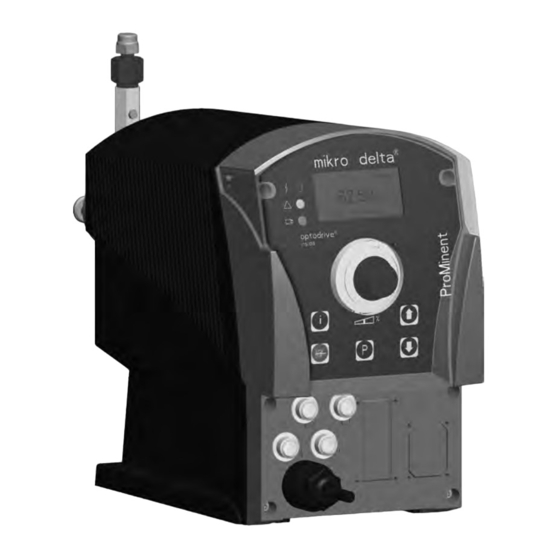
Device overview and control elements Device overview and control elements 5.1 Device overview P_DE_0005_SW Fig. 2 Control unit Drive unit Liquid end P_DE_0028_SW Fig. 3 Back pressure valve Vent screw Discharge valve Suction valve Protective bush Threaded hole for grounding screw... -
Page 16: Control Elements
Device overview and control elements 5.2 Control elements P_DE_0018_SW Fig. 4: a) Displays and keys, b) Electrical control connections LCD display Stroke length adjustment knob [UP] [DOWN] [STOP/START] Operating indicator (green) Warning indicator (yellow) 10 Fault indicator (red) 11 "External control" jack 12 "Dosing monitor"... -
Page 17: Stroke Length Adjustment Knob
Device overview and control elements Application In continuous displays (operation) In adjustment mode (set up) B0098 Pressed 1x Change between the continuous Change between "Changing displays individual numbers" and "Changing a number" Pressed 2x Under "Changing individual numbers": jump to the first number Press and hold Change to the secondary display... - Page 18 Device overview and control elements Symbol Additional Name Meaning symbol Double arrow the value in the continuous display can be changed symbol: with the arrow keys. Info symbol: It is possible to change between continuous dis‐ plays. [STOP/START] Stop: The pump was stopped using the key (i.e.
- Page 19 Device overview and control elements Symbol Additional Name Meaning symbol ‘Analog’ . Line: The pump is in operating mode ‘Curve’ - ‘Line’ is set. The processing type ‘Analog’ . Upper sideband: The pump is in operating mode ‘Curve’ - ‘Upper sideband’ is The processing type set.
-
Page 20: Functional Description
Functional description Functional description 6.1 Liquid end The dosing process is performed as follows: The piston is pressed into the dosing head; the pressure in the dosing head closes the suction valve and the feed chemical flows through the discharge valve out of the dosing head. -
Page 21: Operating Modes
Functional description Data Value Unit Recommended stroke length 4 ... 100 % The stroke speed can be set in the "Dosing" menu. 6.4 Operating modes Operating modes are selected via the "Operating modes" menu. "Manual" operating mode The stroke rate is set manually via the control unit. "Batch"... -
Page 22: Relay (Options)
Functional description "Level switch" function Information about the liquid/powder level in the feed chemical con‐ tainer is reported to the pump. To do so, a two-stage level switch must be fitted; it is connected to the "Level switch" jack. "Pause" function The pump can be remotely stopped via the "External control"... -
Page 23: Led Indicators
Functional description 6.9 LED indicators Fault indicator (red) The fault indicator lights up if the liquid level in the chemical feed container falls below the second switching point of the level switch (20 mm residual filling level in the chemical feed container). This LED flashes in the event of an undefined operating mode. -
Page 24: Assembly
Assembly Assembly WARNING! Danger of electric shock If water or other electrically conducting liquids pene‐ trate into the drive housing, in any other manner than via the pump's suction connection, an electric shock may occur. – Position the pump so that it cannot be flooded. CAUTION! Danger from incorrectly operated or inadequately maintained pumps... -
Page 25: Hydraulic Installation
Hydraulic installation Hydraulic installation Notes CAUTION! Small quantities of feed chemical can escape Due to its design, small quantities of feed chemical escape at the piston. Therefore appropriate safety pre‐ cautions must be taken if toxic media are being metered. –... - Page 26 UNF 1/4"-28 Installing PTFE hose on stainless steel liquid end Max. operating pressure 6 bar for 1/8“ and 1/16“ PTFE hose, valid for connector system on pipe nipple with mikro delta ® Plug the PTFE hose onto the pipe nipple.
- Page 27 Hydraulic installation Installing stainless steel pipe Fig. 8: Installing stainless steel pipe Stainless steel pipe 1/8" or 1/16" Thrust collar 1/8" or 1/16" Tensioning collar 1/8" or 1/16" Connecting nut 1/8" or 1/16" Preparation: Remove the hose with the nipple from the liquid end. Push the connecting nut, thrust collar and the tensioning collar onto the pipe.
-
Page 28: Electrical Installation
Electrical installation Electrical installation WARNING! Danger of electric shock A mains voltage may exist inside the device. – Before any work, disconnect the device's mains cable from the mains. WARNING! Risk of electric shock This pump is supplied with a grounding conductor and a grounding-type attachment plug. -
Page 29: Supply Voltage Connector
Electrical installation CAUTION! Risk of short circuiting caused by moist pins No moisture must reach the pins of the PROFIBUS ® jack. – A suitable PROFIBUS ® plug or protective cap must be screwed onto the PROFIBUS ® jack. CAUTION! Material damage possible due to power surges Should the pump be connected to the mains power supply in parallel to inductive consumers (such as sol‐... -
Page 30: Description Of The Jacks
Electrical installation 9.2 Description of the jacks 9.2.1 "External control" terminal The "external control" jack is a five-pin panel jack. It is compatible with two- and four-conductor cables. The "Auxiliary frequency" and "mA-output" functions can only be used with a five conductor cable. Electrical interface for pin 1 "Pause"... -
Page 31: Level Switch" Terminal
Electrical installation The pump works if: the cable is connected and pin 1 and pin 4 are connected. no cable is connected. "External contact" operating mode The pump performs one or more strokes if: Pin 2 and pin 4 are connected to each other for at least 20 ms. At the same time, pin 1 and pin 4 must also be connected to each other. -
Page 32: Relay
Electrical installation Data Value Unit Voltage with open contacts Input resistance 10 kΩ Control via: potential-free connection contact (load: 0.5 mA at 5 V) or P_DE_0009_SW Fig. 13: Pump pin assignments Function 4-conductor cable Power supply (5 V) brown Coding white Feedback blue... -
Page 33: Output Pacer Relay (Identity Code 4 + 5)
Electrical installation Indentity code 4 + 5 Pin assignment To pin VDE cable Contact Relay yellow NO (normally open) Fault indi‐ P_SI_0044 cating relay Fig. 17: Cable conductor assignments green C (common) Fault indi‐ cating relay white NO (normally open) Pacing relay brown... -
Page 34: Set-Up
Set-up Set-up Please read the overviews in the appendix, "Con‐ – trol elements and key functions" and "Operating/ setting diagram" for supplementary information. If no key is pressed for a 1 minute duration, the – pump returns to a continuous display. 10.1 Basic principles of control adjustment = adjustment option... -
Page 35: Changing To Adjustment Mode
Set-up [i] ("i" for "Info"), if the pump is displaying a Press the key continuous display (The display does not contain the symbol [P] key). for the [i] key, you see another contin‐ ð Each time you press the uous display, an "i" can be seen at the top left. The number of continuous displays depends on the identity code, the selected operating mode and the connected additional devices, see overview "Contin‐... -
Page 36: Selecting The Operating Mode (Menu "Operation")
Set-up Menu Mode Menu Settings Analog Continuous Main display Mode Settings Security Clear Menu Security Menu Clear Menu Language 10.4 Selecting the operating mode (Menu "Operation") ‘Operation’ menu (dependent on the identity code, some In the operating modes may not be present) the following operating modes can be selected: ‘Manual’... -
Page 37: Manual" Operating Mode Settings
Set-up ‘Dosing’ ‘System’ Ä Chapter 10.6 ‘Programmable function For further details, see settings ("Settings" menu )’ on page 44 As to whether or not a further setting menu is available, depends on the selected operating mode and the connected devices or modules. -
Page 38: Settings For The "Batch" Operating Mode (Batch Menu)
Set-up 10.5.2 Settings for the “Batch” operating mode (BATCH menu) Alongside the setting menus, which are described in more detail in Ä Chapter 10.6 ‘Programmable function settings ("Settings" menu )’ on page 44 , in ‘Batch’ operating mode in the ‘Settings’ ‘BATCH’... -
Page 39: Contact" Operating Mode Settings
Set-up 10.5.3 "Contact" operating mode settings Alongside the setting menus, which are described in more detail in Ä Chapter 10.6 ‘Programmable function settings ("Settings" menu )’ on page 44 , in ‘Contact’ operating mode in the ‘Settings’ ‘Contact’ menu is also available. menu, the ‘Contact’... - Page 40 Set-up Example table Factor Pulse (sequence) Number of strokes (sequence) Step-up* 99.99 99.99 1.50 1.50 (1 / 2) 1.25 1.25 (1 / 1 / 1 / 2) Reduction** 0.50 0.10 0.01 0.25 0.40 2.5 (3 / 2) (1 / 1) 0.75 1.33 (2 / 1 / 1) (1 / 1 / 1)
-
Page 41: Analog" Operating Mode Settings
Set-up Non-processed pulses The number of received pulses, which could not yet be processed, is stored by the pump in the stroke memory. When the [STOP/START] key is pressed or the "Pause" function is activated, the stroke memory is deleted. You can avoid this with the "Memory"... - Page 42 Set-up The maximum stroke rate can only be reduced under processing type ‘Curve’ , not under processing types "0 .. 20" and "4 .. 20". Analog Analog Analog Main Settings Analog Mode Analog 0..20mA Settings 4..20mA Concentration Security Auxiliar Curve Clear Calibration 0..20...
- Page 43 Set-up I [mA] B0088 Fig. 21: Rate(frequency)-Current Diagram for Linear control Plot a diagram similar to the one above - with values for (I1, F1) and (I2, F2) – so that you can set the pump as desired! ‘Alarm message’ (fault) your can activate a Fault processing Under the menu option ‘Curve’...
-
Page 44: Programmable Function Settings ("Settings" Menu )
Set-up 10.6 Programmable function settings ("Settings" menu ) Setting menus are available in all operating modes in the menu "SETTINGS" for the following programmable functions: ‘AUX’ ) Auxiliary frequency (menu ‘FLOW’ ) (only available if a dosing monitor is con‐ Flow (menu nected) ‘CALIBRATE’... -
Page 45: Settings For The "Calibrate" Function (Calibrate Menu)
Set-up back message remains missing in a sequence as often as set in ‘FLOW’ under ‘Tolerance’ (due to a failure or too low a the menu metering level), then this function stops the pump. The last menu option provides the choice, of whether this case should lead to a ‘Fault’... -
Page 46: Settings For The "Metering" Function (Dosing Menu)
Set-up Lead the suction hose into a measuring cylinder containing the feed chemical - the discharge hose must be installed in a permanent manner (operating pressure, ...!). Prime using the feed chemical (simultaneously press the two [arrow keys] ), should the suction hose be empty. Record the level in the measuring cylinder. - Page 47 Set-up Discharge stroke Hence the user can, dependent on requirements, set a fast dis‐ ‘Metering’ - ‘fast’ ) for pulsed metering e.g. for quick charge stroke ( clocked filling processes ( a) ) or a slow discharge stroke ‘Metering’ - ‘slow’ ) for quasi-continuous metering, e.g. for pro‐ cesses requiring good mixing ( b) ).
-
Page 48: Settings For The "Relay" Function (Relay Menu)
Set-up The metering behaviour of the pump can be matched to the vis‐ cosity of the feed chemical. Viscosity in mPa "Dosing" setting Suction stroke Max. stroke rate Remarks slowing 0...50 "normal" none 50...200 "HV1" slight for valves with springs 200...500 "HV2"... - Page 49 Set-up You can reprogram the relays using the "Relay" function in an almost limited way. Exception: The two 8 A fault indicating relays (under identity code: 1 and 2) and the 8 A cut-off relays (under ‘NO’ to identity code: 6 and 7) can only be reprogrammed from ‘NC’...
-
Page 50: Settings For The "Analog Output" Function (Analog Output Menu)
Set-up The following table summarises once more the behaviour of the deliverable relay types according to the identity code in the as- delivered condition: Relay type behaviour according to identity code Relay type System response Warning indicating relay ... switches upon a warning alert (yellow LED*). Fault indicating relay ... -
Page 51: Settings In The "System" Menu" (System Menu)
Set-up - Output current in mA - Stroke rate in strokes/min - Stroke length in % fmax - Maximum stroke rate in strokes/min ‘Contact’ and ‘Batch’ operating modes, f is the stroke rate In the which is set in the "Stroke rate" continuous display. 10.6.7 Settings in the "System"... -
Page 52: Set Code (Security Menu)
Set-up 10.7 Set code (SECURITY menu) Batch Batch Batch Main Security Lock Menu Mode none Code: 2793 Settings Lock Menu Security Lock all Clear Continuous display ‘SECURITY’ menu, you can enter whether you want to In the block sections of the adjustment options. ‘None’... -
Page 53: Delete Total Number Of Strokes Or Total Litres (Clear Menu)
Set-up 10.8 Delete total number of strokes or total litres (CLEAR menu) Batch Batch Main Clear Mode none Settings Counter Security Quantity Clear Count+Quantity Continuous display ‘DELETE’ menu, you can either delete the stored total In the number of strokes or the total litres or both together (= reset to "0"): ‘None’... -
Page 54: Operation
Operation Operation WARNING! Warning of crushing of the fingers The moving parts in the turrent can crush fingers. – The protective bush on the liquid end must always be closed when the pump is ready for operation. CAUTION! If the vent screw is open, feed chemical escapes. –... -
Page 55: Manual
Operation 11.1 Manual Personnel: Instructed personnel Adjusting the stroke length The pump may demonstrate unexpected behaviour during operation. Do not set the stroke length adjustment knob to – more than 100 %. The stroke length is adjusted by the stroke length adjustment knob within a range of 0 ... - Page 56 Operation [STOP/START] key again. Start the pump: press the ‘Batch’ operating mode: briefly press key [P] . Start batch [P] key is pressed for 2 seconds in a continuous display, the Changing to adjustment mode If the delta changes to adjustment mode - see chapter "Adjustment". ®...
-
Page 57: Remote Operation
Operation Continuous display Pump stop/start STOP START Change directly alterable variables Priming Start batch (only in "Batch" operating mode) Acknowledge error Check adjustable variables = Security lock ("Lock Menu") Adjustment = Security lock ("Lock all") mode Fig. 26: Operating options with a locked operating menu 11.2 Remote operation There is an option to control the pump remotely via a signal cable -... -
Page 58: Maintenance
Maintenance Maintenance WARNING! It is mandatory that you read the safety information and specifications in the "Storage, Transport and Unpacking" chapter prior to shipping the pump. CAUTION! Warning of feed chemical spraying around Feed chemical can spray out of the hydraulic compo‐ nents if they are manipulated or opened due to pres‐... - Page 59 Maintenance Fig. 27: Leakage hole...
-
Page 60: Overhaul
Unauthorised repairs inside the pump can result in an electric shock. For this reason repairs inside the pump may only be performed by a ProMinent subsidiary or representa‐ tive, in particular the following: – Replacement of damaged mains connection lines –... - Page 61 Overhaul Take off the liquid end from the drive The liquid end may only be mounted later, after the valves have been screwed in. Otherwise the con‐ necting point between the liquid end and valve may subsequently become untight. To do this, the liquid end must first be removed from the drive.
- Page 62 Overhaul Material version Tightening instruction approx. 30 ... 45° approx. 45° or approx. 9 ... 10 With new seals tighten the valves approx. 90 ... 120°. Cleaning a suction valve A suction valve is constructed in almost the same way as a dis‐ charge valve.
-
Page 63: Replacing Liquid End Parts
Overhaul 13.2 Replacing liquid end parts Personnel: Technical personnel Dismantling the dosing head If necessary, use protective equipment. Disconnect the pump from the mains power supply and secure to prevent switching on again. Depressurise the system. Empty the liquid end: Unscrew the back pressure valve from the discharge valve starting slowly (to release the pressure). - Page 64 Overhaul ⑤ Take the dosing head (2) with piston (1) off from the pump. Fitting of packing and piston P_DE_0025_SW Fig. 29 V-sleeve set Pressure plate Shim Disc springs Friction washer Screws Piston TTT, TTG: SST, SSG: Type 100150 „A“ „A“...
- Page 65 Overhaul Check dimension "A", if necessary insert the shim (3). Dimension "A" - in mm Type 100150 100600 101500 600150 400600 201500 Precisely observe the arrangement of the disc springs. Insert the disc springs (4) precisely as shown. Position the friction washer (5). Screw the screws (6) in by hand - do not overtighten! Carefully insert the piston (7).
- Page 66 Overhaul Fitted dosing head Fig. 31 Piston Coupling disc Knurled screws 10 Protective bush 11 Coupling screws Carefully pull the piston (7) out far enough, so that the cou‐ pling disc (8) with its longitudinal holes can project over the heads of the coupling screws (11).
-
Page 67: Troubleshooting
Troubleshooting Troubleshooting Safety information WARNING! Warning of hazardous or unknown feed chemical Should a hazardous or unknown feed chemical be used, it may escape from the hydraulic components when working on the pump. – Take appropriate protective measures before working on the pump (protective eyewear, protec‐ tive gloves, ...). -
Page 68: Fault Alerts
Troubleshooting 14.2 Fault alerts Fault description Cause Remedy Personnel The red LED indicator illuminates, the The liquid level in the Fill the storage tank Technical storage tank has personnel "Level" symbol flashes in the LCD display, the "Fault" and "Stop" symbols reached "liquid level low 2nd stage". -
Page 69: Warning Alerts
The liquid level in the storage Fill the storage Instructed per‐ tank has reached "liquid level tank sonnel the "Level" symbol appears flashing in the LCD display. low 1st stage". 14.5 All Other Faults Please contact the responsible ProMinent subsidiary or represen‐ tative! -
Page 70: Decommissioning
Decommissioning Decommissioning Decommissioning WARNING! Danger from chemical residues There is normally chemical residue in the liquid end and on the housing after operation. This chemical res‐ idue could be hazardous to people. – It is mandatory that the safety information relating to the "Storage, transport and unpacking"... - Page 71 Decommissioning Disposal CAUTION! Warning of feed chemical spraying around Feed chemical can spray out of the hydraulic compo‐ nents if they are manipulated or opened due to pres‐ sure in the liquid end and adjacent parts of the system. – Disconnect the pump from the mains power supply and ensure that it cannot be switched on again by unauthorised persons.
-
Page 72: Technical Data
Technical data Technical data 16.1 Performance data mikro delta b operating at 100 ® strokes/minute and 100 % stroke length Liquid end type Minimum pump capacity Piston diameter Stroke rate at maximum back pressure ml/h µl/stroke Strokes/min 100150 TT 24.17 100600 TT 96.67... -
Page 73: Material Data
Technical data Viscosity in mPa "Dosing" setting Suction stroke Max. stroke rate Remarks slowing 200...500 "HV2" medium for valves with springs 500...1000 "HV3" Maximum for valves with springs The viscosities were measured using silicone oil (Newtonian liq‐ uids) with a 0.5 m suction line. For the adjustment for slowing the suction stroke dependent upon the feed chemical viscosity - see the "Adjustment"... -
Page 74: Temperatures
Technical data 16.5 Temperatures Pump, compl. Data Value Unit Storage and transport temperature –10 ... +50 °C Ambient temperature in operation –10 ... +45 °C (drive and control): Liquid end, long-term* Data Value Unit Liquid end temperature -10 ... +45 °C * long term at max. -
Page 75: Weight
Technical data 16.8 Weight Material version Weight 16.9 Sound pressure level Sound pressure level Sound pressure level LpA < 70 dB in accordance with EN ISO 20361:2010-10 at maximum stroke length, maximum stroke rate, maximum back pressure (water) -
Page 76: Dimensions Sheets
Dimensions sheets Dimensions sheets Dimensions sheet delta ® , material ver‐ sions TT and SS 138.3 196.3 P_DE_0034_SW Fig. 32: Dimensions sheet delta ® MDLa, material versions TT and SS - dimensions in mm Material ver‐ sions TT 100150 243.9 150.1 105.1 159.1... -
Page 77: Diagrams For Setting The Metering Capacity
Diagrams for setting the metering capacity Diagrams for setting the metering capacity C [ml/h] MDLa 100150 f [%] C [ml/h] MDLa 101500 f [%] 1500 100 min 50 min 100 min 50 min 1250 40 min 40 min 90 min 90 min 80 min 30 min... - Page 78 Diagrams for setting the metering capacity C [ml/h] MDLa 600150 f [%] C [ml/h] MDLa 201500 f [%] 1500 100 min 50 min 100 min 50 min 1250 40 min 40 min 90 min 90 min 80 min 30 min 80 min 30 min 70 min...
-
Page 79: Exploded View Drawings
Exploded view drawings Exploded view drawings Liquid end mikro delta ® 100150 - 101500, TT 116/118 116/117 P_DE_0036_SW Fig. 35: Liquid end mikro delta ® 100150 - 101500, TT... - Page 80 Exploded view drawings Liquid end mikro delta ® 600150 - 201500, SS 111/112 116/118 116/118 116/117 P_DE_0035_SW Fig. 36: Liquid end mikro delta 600150 - 201500, SS ®...
-
Page 81: Ordering Information
Ordering Information Ordering Information Spare parts list TT_ Legend: A, B - Type 100150 C, D - Type 100600 E, F - Type 101500 ______________________________________________________________ _ _____________________________________________________________ _ Pos.Typ Anz. Artike l Description Best.Nr. Pos.Type No. o f Code No . ______________________________________________________________ _ _____________________________________________________________ _ MDLa Fördereinheiten T T... - Page 82 Ordering Information Pos.Typ Anz. Artike l Description Best.Nr . Pos.Type No. o f Code No . ______________________________________________________________ _ _____________________________________________________________ _ MDLa Fördereinheiten T T MDLa Liquid ends TT ______________________________________________________________ _ _____________________________________________________________ _ 469438 119 C-D ** 4,000 Ventilfeder d0.3/DA 4.0 0.1bar 1.4571 Valve spring d0.3/DA 4.0 0.1bar 1.4571 119 E-F ** 4,000 Ventilfeder d0.4/DA 4.9 0.1bar...
- Page 83 Ordering Information Spare parts list SS_ Legend: A, B - Type 600150 C, D - Type 400600 E, F - Type 201500 ______________________________________________________________ _ _____________________________________________________________ _ Pos.Typ Anz. Artike l Description Best.Nr . Pos.Type No.o f Code No . ______________________________________________________________ _ _____________________________________________________________ _ MDLa Fördereinheiten S S MDLa Liquid ends...
- Page 84 Fig. 40: Spare parts list SS_, S. 2 Further sources of information Further information on spare parts, accessories and options can be found in: the exploded drawings the identity code the "General Operating Instructions on ProMinent solenoid ® dosing pumps". the ProMinent Equipment catalogue...
-
Page 85: Ec Declaration Of Conformity
EC Directive, by virtue of its design and construction, and in the configuration placed on the market by us. This declaration is no longer applicable if changes are made to the product without our authorisation. Dosing pump, mikro delta series Product description: MDLa…... -
Page 86: Decontamination Declaration
Decontamination declaration Decontamination declaration... -
Page 87: Operating / Adjustment Overview
Operating / adjustment overview Operating / adjustment overview Continuous display Pump stop/start STOP START Change directly alterable variables Priming Start batch (only in "Batch" operating mode) Acknowledge error Check adjustable variables Analog Menu Main Mode Mode Settings Security Clear Menu Menu Settings Op. - Page 88 Operating / adjustment overview Menu Security Menu Clear Menu Language...
-
Page 89: Continuous Displays
Continuous displays Continuous displays... - Page 90 Continuous displays...
-
Page 91: Index
Index Index Disposal............... 71 ................. 63 Dosing head............63 " Dosing monitor............. 31 "Diaphragm rupture reporter" jack......16 "Dosing monitor" jack........... 16 Emergency............11 "External control" jack.......... 16 Emptying the liquid end........70 "External control" terminal........30 Explanation of the safety instructions....8 "Level Switch"... - Page 92 Index Linear..............42 Safety requirements..........74 Scope of supply............ 14 Mains Cable............29 Secondary displays..........35 Maintenance............58 SECURITY............52 Manual............. 21, 23, 37 Semiconductor switch.......... 33 Manual operation..........55 Serial number SN..........51 mA Output............22, 30 Sideband.............. 43 Memory............
- Page 96 Im Schuhmachergewann 5-11 69123 Heidelberg Germany Telephone: +49 6221 842-0 Fax: +49 6221 842-617 email: info@prominent.com Internet: www.prominent.com 986161, 3, en_GB " ром им ех" офици льный п ртнер и пост вщик н сосов ProMinent www.promhimtech.ru / zakaz@promhimtech.ru © 2010...
Need help?
Do you have a question about the mikro delta and is the answer not in the manual?
Questions and answers