Sign In
Upload
Manuals
Brands
Intel Manuals
Server
M20NTP1UR
Intel M20NTP1UR Manuals
Manuals and User Guides for Intel M20NTP1UR. We have
1
Intel M20NTP1UR manual available for free PDF download: System Integration And Serive Manual
Intel M20NTP1UR System Integration And Serive Manual (114 pages)
Brand:
Intel
| Category:
Server
| Size: 11 MB
Table of Contents
Table of Contents
7
Introduction
13
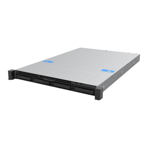
Figure 1. Intel® Server System M20NTP1UR
13
Reference Documents and Support Collaterals
15
Table 1. Intel® Server System M20NTP1UR Reference Documents and Support Collaterals
15
Essential System Component Installation
17
Figure 2. Intel® Server System M20NTP1UR Features
17
System Top Cover Removal / Installation
18
System Top Cover Removal
18
Figure 3. System Top Cover Screws
18
Figure 4. System Cover Removal
18
System Top Cover Installation
19
Figure 5. System Cover Installation
19
Air Duct Removal and Installation
20
Air Duct Removal
20
Air Duct Installation
20
Figure 6. Air Duct Removal
20
Figure 7. Air Duct Installation
20
2.3 Processor Assembly and Installation
21
Figure 8. Processor Heat Sink Module (PHM) Reference Diagram
21
PHM Assembly
22
Figure 9. Installing Processor Carrier Clip Onto Processor - Part 1
22
Figure 10. Installing Processor Carrier Clip Onto Processor - Part 2
22
Figure 11. Processor Heat Sink Handling
23
Figure 12. Processor Heat Sink Anti-Tilt Wires in the Outward Position
23
Figure 13. Pin 1 Indicator of Processor Carrier Clip
23
PHM Installation
24
Figure 14. Processor Socket Cover Removal
24
Figure 15. PHM Alignment with Processor Socket Assembly
24
Figure 16. PHM Installation Onto Server Board
25
Figure 17. Tighten Heat Sink Fasteners
25
Memory Module Installation
26
DIMM Installation
26
Figure 18. DIMM Blank Removal
26
Figure 19. Memory Module Installation
26
System Options / Accessory Kit Installation
28
System Top Cover Removal / Installation
28
System Top Cover Removal
28
Figure 20. System Top Cover Screws
28
System Top Cover Installation
29
Figure 21. System Cover Removal
29
Figure 22. System Cover Installation
29
Air Duct Removal and Installation
30
Air Duct Removal
30
Air Duct Installation
30
Figure 23. Air Duct Removal
30
Figure 24. Air Duct Installation
30
Power Supply Module Installation
31
Pcie* Add-In Card Installation
31
Figure 25. Power Supply Installation
31
Figure 26. Riser Card Bracket Removal
32
Figure 27. Pcie* Add-In Card Installation
32
Front Drive Installation
33
Figure 28. Riser Card Assembly Installation
33
Front Drive Removal
34
Figure 29. Extracting Drive Carrier from Chassis
34
Figure 30. 3.5" Drive Blank Removal
34
3.5" Drive Assembly
35
Figure 31. 3.5" Drive Installation to Drive Carrier
35
Figure 32. 3.5" Drive Blank to 2.5" SSD Mounting Bracket Conversion
35
Figure 33. 2.5" SSD Mounting Bracket Assembly
36
Figure 34. 3.5" Drive Carrier to 2.5" SSD Bracket - Mount Bracket Assembly to Carrier
36
Front Drive Installation
37
Figure 35. Secure 2.5" SSD Assembly to Drive Carrier
37
Figure 36. Drive Carrier into Chassis Installation
37
Nvme* SSD Support
38
Figure 37. Nvme* Support Cable Connectors
38
Table 2. Pcie* Nvme* Cable Routing
38
M.2 SSD Installation
39
Figure 38. Nvme* Cable Kit Routing
39
Figure 39. M.2 Mounting Latch Placement
40
Figure 40. M.2 SSD Installation
40
Ethernet Network Adapter for OCP* - Installation
41
Figure 41. OCP* Adapter Bay Filler Removal
41
Figure 42. OCP* Mounting Bracket Installation
41
Figure 43. OCP* Module Mounting Screws
42
Figure 44. OCP* Module Installation
42
Trusted Platform Module (TPM) Installation
43
Figure 45. TPM Placement
43
3.10 Intel® VROC 7.5 Key Installation
44
Figure 46. Intel® VROC Key Installation
44
System Software Updates and Configuration
45
System Service - System Features Overview
46
Table 3. Intel® Server System M20NTP1UR Features
46
Figure 47. System Features
48
Figure 48. Back Panel Features
49
Figure 49. Front Panel Features
49
Figure 50. Backplane Cable Connectors
49
Figure 51. Control Panel Features
49
System Status LED State Identification
50
Table 4. System Status LED State Definitions
50
Server Board Jumper Blocks and Service Buttons
51
PC Beep Jumper
51
BMC COM Port Configuration Jumpers
51
ME Recovery Jumper
51
Figure 52. Server Board Jumper Blocks and Service Buttons
51
Support Requirements for Thermal Management
52
Figure 53. System Airflow
52
Figure 54. DIMM Blank
52
System Service and FRU Replacement
53
System Top Cover Removal / Installation
54
System Top Cover Removal
54
Figure 55. System Top Cover Panel Shipping Screws
54
Figure 56. System Cover Removal
54
System Top Cover Installation
55
Figure 57. System Cover Installation
55
Air Duct Removal and Installation
56
Air Duct Removal
56
Air Duct Installation
56
Figure 58. Air Duct Removal
56
Figure 59. Air Duct Installation
56
Memory Module Replacement
57
Figure 60. Memory Module Removal
57
Figure 61. DIMM Installation
57
System Fan Replacement
58
Figure 62. System Fan Assembly Removal
58
Power Supply Replacement
59
Figure 63. System Fan Assembly Installation
59
Figure 64. Power Supply Removal
59
Front Drive Replacement
60
Drive Carrier Extraction
60
Figure 65. Power Supply Installation
60
Figure 66. Extracting Drive Carrier from Chassis
60
3.5" Drive Replacement
61
Figure 67. 3.5" Drive Removal from Drive Carrier
61
Figure 68. 3.5" Drive Installation to Drive Carrier
61
Drive Replacement
62
Figure 69. 2.5" Drive Mounting Bracket Removal from Drive Carrier (Step 1)
62
Figure 70. 2.5" Drive Mounting Bracket Removal from Drive Carrier (Step 2)
62
Figure 71. 2.5" Drive Removal from Mounting Bracket
62
Figure 72. 2.5" Drive Installation to Mounting Bracket
63
Figure 73. 2.5" Drive Assembly Installation to Drive Carrier (Step 7)
63
Front Drive Installation
64
Figure 74. 2.5" SSD Assembly Installation to Drive Carrier (Step 8)
64
Figure 75. Drive Carrier into Chassis Installation
64
Riser Card Replacement
65
Figure 76. Riser Card Bracket Removal
65
Figure 77. Pcie* Add-In Card Removal
65
Figure 78. Riser Card Removal from Bracket
66
Figure 79. Riser Card Installation
66
Figure 80. Pcie* Add-In Card Installation
66
Figure 81. Riser Card Assembly Installation
67
OCP* Module Replacement
68
Figure 82. OCP* Module Removal
68
Figure 83. OCP* Module Installation
69
Backplane Replacement
70
Figure 84. Backplane Removal (Step 1)
70
Figure 85. Backplane Removal (Step 2)
70
Figure 86. Backplane Removal (Step 3)
71
Figure 87. Backplane Installation (Step 1)
71
Figure 88. Backplane Installation (Step 2)
72
Figure 89. Backplane Installation (Step 3)
72
6.10 M.2 SSD Replacement
73
Figure 90. M.2 SSD Removal
73
Figure 91. M.2 SSD Installation
73
6.11 Intel® VROC 7.5 (VMD Nvme* RAID) Key Replacement
74
Figure 92. Intel® VROC Key Removal
74
Figure 93. Intel® VROC Key Installation
74
6.12 System Battery Replacement
75
Figure 94. System Battery Removal
75
Figure 95. System Battery Installation
75
6.13 Processor Replacement
76
Figure 96. PHM Assembly Removal from Processor Socket
76
Figure 97. Processor Socket Cover Installation
77
Figure 98. PHM Disassembly
78
Figure 99. Processor Carrier Clip Removal from PHM Assembly
78
Figure 100. Installing Processor Carrier Clip Onto Processor - Part 1
79
Figure 101. Installing Processor Carrier Clip Onto Processor - Part 2
79
Figure 102. Processor Heat Sink Handling
80
Figure 103. Processor Heat Sink Anti-Tilt Wires in the Outward Position
80
Figure 104. Processor Heat Sink Placement
80
Figure 105. Processor Socket Cover Removal
81
Figure 106. PHM Alignment with Processor Socket Assembly
81
Figure 107. PHM Installation Onto Server Board
82
Figure 108. Tighten Heat Sink Fasteners
82
6.14 Server Board Replacement
83
Figure 109. Server Board Removal
83
Figure 110. Server Board Installation
84
Appendix A. Getting Help
85
Appendix B. Internal Cable Routing Channels
86
Figure 111. Cable Routing Channels
86
Appendix C. Memory Population Rules
87
Figure 112. Server Board Memory Slot Association by CPU
87
Figure 113. Processor Memory Slot Support Overview
87
Recommended Memory Configurations
88
Table 5. Recommended DDR4 DIMM Per Socket Population Configurations
88
Table 6. DDR4 DIMM Attributes Table for "Identical" and "Like" Dimms
89
Appendix D. POST Code Errors
90
Appendix E. System Packaging Assembly Instructions
96
Appendix F. Safety Instructions
99
Appendix G. Glossary
114
Advertisement
Advertisement
Related Products
Intel M20MYP1UR
Intel MFSYS25V2
Intel MFSYS35
Intel MFS5520VIBR
Intel MFS5520VIR
Intel MFS2600KIB
Intel MB440LX
Intel M70KLP Series
Intel M50CYP1UR Series
Intel M50CYP2UR Series
Intel Categories
Motherboard
Computer Hardware
Server
Desktop
Server Board
More Intel Manuals
Login
Sign In
OR
Sign in with Facebook
Sign in with Google
Upload manual
Upload from disk
Upload from URL