Table of Contents
Advertisement
Quick Links
Advertisement
Table of Contents

Related Manuals for Intel M50CYP2SB Series


Summary of Contents for Intel M50CYP2SB Series
- Page 1 Intel® Server Board M50CYP2SB Family Technical Product Specification An overview of product features, functions, architecture, and support specifications. Rev. 1.3 September 2021 Delivering Breakthrough Data Center System Innovation – Experience What’s Inside!
- Page 2 <This page intentionally left blank>...
- Page 3 • Table 7. Updated row for Silver 4300 processors • Section 7.3.1. Updated text descriptions • Section 8.1.4. Added section on “Intel® Virtual RAID on Chip (Intel® VROC) for SATA” • Appendix H. Updated Tables 56 and 57 • Minor updates throughout for clarity •...
- Page 4 You may not use or facilitate the use of this document in connection with any infringement or other legal analysis concerning Intel products described herein. You agree to grant Intel a non-exclusive, royalty-free license to any patent claim thereafter drafted which includes subject matter disclosed herein.
-
Page 5: Table Of Contents
Memory Subsystem Architecture ..........................39 Supported Memory ............................... 39 4.2.1 Standard DDR4 DIMM Support ..........................40 4.2.2 Intel® Optane™ Persistent Memory 200 Series Module Support ............... 41 Memory Population ............................... 43 4.3.1 DDR4 DIMM Population Rules ..........................44 4.3.2 Intel® Optane™ Persistent Memory 200 Series Module Rules ..............45 4.3.3... - Page 6 PCIe* Riser Card Support ............................74 PCIe* Interposer Riser Slot (Intel® Server Board M50CYP2SB1U Only) ..........74 7.3.1 PCIe* Interposer Riser Card Usage in an Intel® Server System M50CYP1UR Family ......75 8. Storage Support ................................ 77 Server Board SATA Support ............................77 8.1.1...
- Page 7 12.6.3 TPM Security Setup Options ..........................105 12.7 Intel® CBnT – Converged Intel® Boot Guard and Trusted Execution Technology (Intel® TXT) ... 106 12.8 Unified Extensible Firmware Interface (UEFI) Secure Boot Technology ..........106 13. Server Board Configuration and Service Jumpers ..................107 13.1...
- Page 8 Figure 8. Intel® Server Board M50CYP2SBSTD and M50CYP2SB1U Board Dimensions ........... 24 Figure 9. Intel® Server Board M50CYP2SB Family Top Surfaces Keep Out Zone (drawing 1) ........25 Figure 10. Intel® Server Board M50CYP2SB Family Top Surface Keep Out Zone (drawing 2) ......... 26 Figure 11.
- Page 9 Figure 21. Standard SDRAM DDR4 DIMM Module ........................40 Figure 22. Intel® Optane™ Persistent Memory 200 Series Module ..................41 Figure 23. <F2> BIOS Setup Screen Navigation for Intel® Optane™ PMem Setup Options ........42 Figure 24. Intel® Optane™ PMem Configuration Menu in <F2> BIOS Setup ..............43 Figure 25.
- Page 10 Figure 59. Exploded View of POST Code Diagnostic, System ID, and System Status LED Area ......92 Figure 60. Memory Fault LED Location ............................95 Figure 61. Fan Fault LEDs (Intel® Server Board M50CYP2SBSTD shown) ................. 96 Figure 62. BIOS Setup Security Tab ............................... 100 Figure 63.
- Page 11 Intel® Server Board M50CYP2SB Family Technical Product Specification Table 7. Intel® Optane™ Persistent Memory 200 Series Module Support ................. 46 Table 8. Standard DDR4 DIMMs Compatible with Intel® Optane™ Persistent Memory 200 Series Module ..46 Table 9. Standard DDR4 DIMM-Only per Socket Population Configurations ..............47 Table 10.
- Page 12 Table 55. Available Sensors Monitored by the BMC ....................... 132 Table 56. Server Board Mounting Screw Torque Requirements ..................136 Table 57. Intel® Server System M50CYP2UR Family Features .................... 148 Table 58. Intel® Server System M50CYP1UR Family Features .................... 152...
-
Page 13: Introduction
Xeon® Scalable processor family. Previous generation Intel® Xeon® processor and Intel® Xeon® Scalable processor families are not supported. The Intel® Server Board M50CYP2SB family is a foundational building block of the server system. The family is backed by Intel design excellence, manufacturing expertise, and world-class support to deliver processing power with high levels of flexibility, manageability, and reliability. -
Page 14: Reference Documents
For additional information, see the product support collaterals specified in the following table. The following webpage provides support information for the M50CYP family: https://www.intel.com/content/www/us/en/support/products/200321.html Table 1. Intel® Server M50CYP Family Reference Documents and Support Collaterals Document Topic Document Title or Support Collateral... - Page 15 Intel® Data Center Manager (Intel® DCM) information Intel® Data Center Manager (Intel® DCM) Console User Guide https://software.intel.com/content/www/us/en/develop/download/dcm- Public user-guide.html Note: Intel Confidential documents are made available under a Non-Disclosure Agreement (NDA) with Intel and must be ordered through your local Intel representative.
-
Page 16: Server Board Family Overview
Gen Intel® Xeon® Scalable processor SKUs must Not end in (H), (L), (U), (Q), or (M). All other processor SKUs are supported. • Intel® UPI links: up to three at 11.2 GT/s (Platinum and Gold families) or up to two at 10.4 GT/s (Silver family) Note: Previous generation Intel®... - Page 17 • PCIe* 4.0 support for 32 GB/s • PCIe* Interposer Riser Slot supports the Intel interposer riser card as an accessory option. This card supports one PCIe* add-in card (x8 electrical, x8 mechanical). The PCIe* interposer riser card can be used only when it is connected to the PCIe* NVMe* riser card in Riser Slot #2 (iPC –...
- Page 18 PCIe* NVMe* Support • Intel® Volume Management Device (Intel® VMD) 2.0 support • Intel® Virtual RAID on CPU 7.5 (Intel® VROC 7.5) support using one of the three types of VROC keys (available as an Intel accessory option) • Integrated 2D video controller Video Support •...
-
Page 19: Server Board Component / Feature Identification
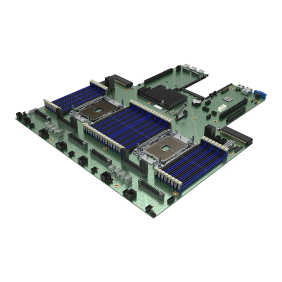
Intel® Server Board M50CYP2SB Family Technical Product Specification Server Board Component / Feature Identification Figure 2. Intel® Server Board M50CYP2SBSTD Component / Feature Identification Note: The features identified in the above figure represent their intended use when the board is integrated... -
Page 20: Figure 3. Intel® Server Board M50Cyp2Sb1U Component / Feature Identification
Intel® Server Board M50CYP2SB Family Technical Product Specification Figure 3. Intel® Server Board M50CYP2SB1U Component / Feature Identification Note: The features identified in the above figure represent their intended usage when the board is integrated into an Intel chassis. The server board includes LEDs to identify system status and/or indicate a component fault. -
Page 21: Figure 4. Intel® Light-Guided Diagnostics - Led Identification
Intel® Server Board M50CYP2SB Family Technical Product Specification Figure 4. Intel® Light-Guided Diagnostics – LED Identification... -
Page 22: Figure 5. Fan Fault Leds On Intel® Server Board M50Cyp2Sb1U
Intel® Server Board M50CYP2SB Family Technical Product Specification Figure 5. Fan fault LEDs on Intel® Server Board M50CYP2SB1U Figure 6. Intel® Light-Guided Diagnostics - DIMM Fault LEDs... -
Page 23: Figure 7. System Configuration And Recovery Jumpers
Intel® Server Board M50CYP2SB Family Technical Product Specification The server board includes several jumper headers (see Figure 7) that can be used to configure, protect, or recover specific features of the server board. For more information on reset and recovery jumpers, see Chapter Figure 7. -
Page 24: Server Board Dimensions
Intel® Server Board M50CYP2SB Family Technical Product Specification Server Board Dimensions The following figure shows the Intel® Server Board M50CYP2SBSTD and M50CYP2SB1U dimensions. Figure 8. Intel® Server Board M50CYP2SBSTD and M50CYP2SB1U Board Dimensions... -
Page 25: Server Board Mechanical Drawings
Intel® Server Board M50CYP2SB Family Technical Product Specification Server Board Mechanical Drawings Figure 9. Intel® Server Board M50CYP2SB op Surfaces Keep Out Zone (drawing 1) Family T... -
Page 26: Figure 10. Intel® Server Board M50Cyp2Sb Family Top Surface Keep Out Zone (Drawing 2)
Intel® Server Board M50CYP2SB Family Technical Product Specification Figure 10. Intel® Server Board M50CYP2SB Family op Surface Keep Out Zone (drawing 2) -
Page 27: Figure 11. Intel® Server Board M50Cyp2Sb Family Bottom Surface Keep Out Zone (Drawing 1)
Intel® Server Board M50CYP2SB Family Technical Product Specification Figure 11. Intel® Server Board M50CYP2SB (drawing 1) Family Bottom Surface Keep Out Zone... -
Page 28: Figure 12. Intel® Server Board M50Cyp2Sb Family Bottom Surface Keep Out Zone (Drawing 2)
Intel® Server Board M50CYP2SB Family Technical Product Specification Figure 12. Intel® Server Board M50CYP2SB (drawing 2) Family Bottom Surface Keep Out Zone... -
Page 29: Figure 13. Intel® Server Board M50Cyp2Sb Family Components Position (Drawing 1)
Intel® Server Board M50CYP2SB Family Technical Product Specification Figure 13. Intel® Server Board M50CYP2SB omponents Position (drawing 1) Family C... -
Page 30: Figure 14. Intel® Server Board M50Cyp2Sb Family Components Position (Drawing 2)
Intel® Server Board M50CYP2SB Family Technical Product Specification Figure 14. Intel® Server Board M50CYP2SB omponents Position (drawing 2) Family C... -
Page 31: Figure 15. Intel® Server Board M50Cyp2Sb Family Holes Position
Intel® Server Board M50CYP2SB Family Technical Product Specification Figure 15. Intel® Server Board M50CYP2SB oles Position Family H... -
Page 32: Server Board Architecture Overview
Intel® Server Board M50CYP2SB Family Technical Product Specification Server Board Architecture Overview The architecture of the Intel® Server Board M50CYP2SB family was developed around the integrated features and functions of the 3 Gen Intel® Xeon® Scalable processor family, Intel® C621A Platform Controller Hub (PCH) chipset, and ASPEED* AST2500 Server Management Processor. -
Page 33: Figure 17. Intel® Server Board M50Cyp2Sb1U Architectural Block Diagram
Intel® Server Board M50CYP2SB Family Technical Product Specification The following figure provides an overview of the Intel® Server Board M50CYP2SB1U architecture, showing the features and interconnects of the major subsystem components. Figure 3 provides a general overview of the physical server board, identifying key feature and component locations. -
Page 34: Processor Support
Xeon® Scalable processor family. The server board supports the processor family with a maximum TDP of 270 W. Note: Previous generations Intel® Xeon® processor and Intel® Xeon® Scalable processor families and their supported processor heat sinks are not compatible on server boards described in this document. -
Page 35: Processor Cooling Requirements
Intel ensures through its own chassis development and testing that when an Intel server board and Intel chassis are used together, the fully integrated system meets the thermal requirements of these components. It is the... -
Page 36: Processor Family Overview
Gen Intel® Xeon® Scalable processor SKUs must Not end in (H), (L), (U), (Q), or (M). All other processor SKUs are supported. * Note: The 8351N SKU is a single-socket optimized SKU and is not supported on the Intel® Server Board M50CYP2SB family. -
Page 37: Supported Technologies
3.3.1 Supported Technologies The 3 Gen Intel® Xeon® Scalable processors combine several key system components into a single processor package including the processor cores, Integrated Memory Controller (IMC), and Integrated IO Module. The core features and technologies for the processor family include: •... -
Page 38: Processor Population Rules
When using a single processor configuration, the processor must be installed into the processor socket labeled “CPU_0”. Note: Some server board features may not be functional unless a second processor is installed. For the Intel® Server Board M50CYP2SBSTD, see Figure 16. -
Page 39: Memory Support
Server boards designed to support the 3 Generation Intel® Xeon® Scalable processors may be populated with a combination of both DDR4 DRAM DIMMs and Intel® Optane™ persistent memory 200 series modules. Note: Previous generation Intel® Optane™ persistent memory modules are not supported. -
Page 40: Standard Ddr4 Dimm Support
Intel® Server Board M50CYP2SB Family Technical Product Specification 4.2.1 Standard DDR4 DIMM Support The following figure shows a standard DDR4 DIMM module. Figure 21. Standard SDRAM DDR4 DIMM Module The server board supports DDR4 DIMMs with the following features: •... -
Page 41: Intel® Optane™ Persistent Memory 200 Series Module Support
Intel® Optane™ persistent memory 200 series module. Figure 22. Intel® Optane™ Persistent Memory 200 Series Module Intel® Optane™ PMem (persistent memory) is an innovative technology that delivers a unique combination of affordable large memory capacity and data persistence (non-volatility). It represents a new class of memory and storage technology architected specifically for data center usage. -
Page 42: Figure 23.
DRAM DIMM, such as database “scratch pads”. Data that needs to be made persistent or structures that are very large can be routed to the Intel® Optane™ persistent memory. The App Direct mode must be used to make data persistent in memory. This mode requires an operating system or virtualization environment enabled with a persistent memory-aware file system.Bios Setup Screen Navigation For Intel® Optane™ Pmem Setup Options -
Page 43: Memory Population
Intel® Server Board M50CYP2SB Family Technical Product Specification The main Intel® Optane™ PMem Configuration screen provides links to the various device information and setup screens. Figure 24. Intel® Optane™ PMem Configuration Menu in <F2> BIOS Setup Memory Population On the server board, a total of 32 memory slots are provided – two slots per channel and eight channels per processor. -
Page 44: Ddr4 Dimm Population Rules
However, Intel may ship back a validated “Like” DIMM. A “Like” DIMM may be from the same vendor but may not be the same revision # or model #, or it may be an Intel validated DIMM from a different vendor. -
Page 45: Intel® Optane™ Persistent Memory 200 Series Module Rules
Intel® Optane™ persistent memory 200 series modules are only supported in DIMM slot 2 (black slot) when mixed with RDIMM or 3DS-RDIMM. • No support for SDRAM SRx8 DIMM that is populated within the same channel as the Intel® Optane™ persistent memory 200 series module in any operating mode. •... -
Page 46: Table 7. Intel® Optane™ Persistent Memory 200 Series Module Support
2933 Platinum 8300 processors 2666 2400 Note: *Gold processor SKU 6330 maximum speed is 2933 (MT/s). Table 8. Standard DDR4 DIMMs Compatible with Intel® Optane™ Persistent Memory 200 Series Module DIMM Size (GB) Ranks per DIMM and Type Data Width... -
Page 47: Recommended Memory Configurations
Intel® Server Board M50CYP2SB Family Technical Product Specification 4.3.3 Recommended Memory Configurations This section provides the recommended memory population configurations for the server board. For best system performance in dual-processor configurations, installed memory type and population should be the same for both processors. -
Page 48: Memory Ras Support
Table 11. This table lists the RAS features pertaining to system memory that has standard DDR4 DIMMs or a combination of standard DDR4 DIMMS and Intel® Optane™ persistent memory 200 series modules. These features are managed by the processor’s IMC. -
Page 49: Table 11. Memory Ras Features
Intel® Server Board M50CYP2SB Family Technical Product Specification Table 11. Memory RAS Features Memory RAS Feature Description Standard Advanced Allows replacing failed single bit within a device using spare capacity available within the processor’s integrated memory controller (IMC). Partial Cache-Line Sparing √... -
Page 50: Table 12. Intel® Optane™ Persistent Memory 200 Series Ras Features
• The Intel® Optane™ persistent memory 200 series RAS features listed in the following table are integrated into the system memory RAS features. The following table lists additional memory RAS features specific to the Intel® Optane™ persistent memory 200 series memory. -
Page 51: Table 13. Compatibility Of Ras Features Intel® Sgx, Intel® Tme, And Intel® Tme-Mt
The Intel® Server Board M50CYP2SB family security feature support includes Intel® Software Guard Extensions (Intel® SGX), Intel® Total Memory Encryption (Intel® TME), and Intel® Total Memory Encryption – Multi-Tenant (Intel® TME-MT). When any of these security features are enabled, Intel® Optane™ PMem 200 series is disabled. -
Page 52: Server Management
Intel® Server Board M50CYP2SB Family Technical Product Specification Server Management Intel® Server Board M50CYP2SB family uses the baseboard management controller (BMC) features of an ASpeed* AST2500 Server Management Processor. The BMC supports multiple system management features including intra-system sensor monitoring, fan speed control, system power management, and system error handling and messaging. -
Page 53: Configuring System Management Port Using
Intel® Server Board M50CYP2SB Family Technical Product Specification 5.1.1 Configuring System Management Port Using <F2> BIOS Setup 1. During the system power-on POST process, press <F2> when prompted to go to the BIOS Setup utility main menu page. 2. Navigate to the Server Management tab and select BMC LAN Configuration to enter the BMC LAN...Bios Setup -
Page 54: Standard System Management Features
Intel® Server Board M50CYP2SB Family Technical Product Specification Figure 29. BIOS Setup User Configuration Screen Once the management port is configured, the server can be accessed remotely to perform system management features defined in the following sections. Standard System Management Features The following system management features are supported on the Intel®... -
Page 55: Integrated Baseboard Management Controller Web Console (Integrated Bmc Web Console)
Intel® Server Board M50CYP2SB Family Technical Product Specification The KVM-redirection feature automatically senses video resolution for best possible screenshot and provides high-performance mouse tracking and synchronization. It allows remote viewing and configuration in pre-boot POST and BIOS Setup once BIOS has initialized video. -
Page 56: Redfish* Support
The BMC update will happen immediately and cause a BMC reset to occur at the end. The BIOS and Intel ME firmware is staged in the BMC and will be updated on the next reboot. The BMC also supports Redfish and embedded web console feature to view and modify BIOS settings. -
Page 57: Autonomous Debug Log
Intel. A license file is then downloaded onto the system where the Integrated BMC Web Console or the SYSCFG utility are used to upload the key to the BMC firmware to unlock the advanced features. -
Page 58: Virtual Media Over Network Share And Local Folder
Intel® Data Center Manager (DCM) Support Intel® DCM is a solution for out-of-band monitoring and managing the health, power, and thermals of servers and a variety of other types of devices. -
Page 59: Server Board Connector / Header Pinout Definition
Intel® Server Board M50CYP2SB Family Technical Product Specification Server Board Connector / Header Pinout Definition This chapter identifies the location and pinout for most connectors and headers on the server board. Information for some connectors and headers is found elsewhere in the document where the feature is described in more detail. -
Page 60: Table 14. Main Power (Slot 1) And Main Power (Slot 2) Connector Pinout ("Main Pwr 1" And "Main Pwr 2")
Intel® Server Board M50CYP2SB Family Technical Product Specification Table 14. Main Power (Slot 1) and Main Power (Slot 2) Connector Pinout (“MAIN PWR 1” and “MAIN PWR 2”) Pin # Signal Name Pin # Signal Name GROUND GROUND GROUND GROUND... -
Page 61: Hot Swap Backplane (Hsbp) Power Connector
Intel® Server Board M50CYP2SB Family Technical Product Specification 6.1.2 Hot Swap Backplane (HSBP) Power Connector The server board includes one white 2x6-pin power connector that, when cabled, provides power for hot swap backplanes. The connector is shown in the following figure. -
Page 62: Optional 12-V Power Connectors
Intel® Server Board M50CYP2SB Family Technical Product Specification 6.1.3 Optional 12-V Power Connectors The server board includes five 2x2-pin power connectors labeled “OPT_12V_PWR”. The connectors provide supplemental 12 V power-out to high-power PCIe* x16 add-in cards that have power requirements that exceed the 75 W maximum power supplied by the riser card slot. -
Page 63: Peripheral Power Connector
Intel® Server Board M50CYP2SB Family Technical Product Specification 6.1.4 Peripheral Power Connector The server board includes one 6-pin power connector intended to provide power for peripheral devices such as solid state devices (SSDs). The power connector supports 3.3, 5, 12 volts. On the server board, this connector is labeled “Peripheral_ PWR”. -
Page 64: Front Usb 3.0/2.0 Panel Header And Front Control Panel Header
Intel® Server Board M50CYP2SB Family Technical Product Specification Front USB 3.0/2.0 Panel Header and Front Control Panel Header The server board includes two headers that provide various front panel options. This section provides the location and pinout for each header. The headers shown in the figure are the same type. The header manufacturer is Hirose Electric* Company (U.S.A.) Incorporated;... -
Page 65: Front Control Panel Header Pinout
Intel® Server Board M50CYP2SB Family Technical Product Specification 6.2.2 Front Control Panel Header Pinout The Front Control Panel header is 26 pins. The following table provides the pinout. Table 19. Front Control Panel Header Pinout Pin # Signal Name Pin #... -
Page 66: I 2 C Connectors
Intel® Server Board M50CYP2SB Family Technical Product Specification Table 20. Serial Port B Header Pinout Pin# Signal Name Pin# Signal Name SOUT GROUND C Connectors The server board contains two I C connectors. The header locations are shown in Figure 38... -
Page 67: Fan Connectors
FAN PWM Fan Tachometer 2 (Sense) In addition to the fan connectors shown above, the Intel® Server Board M50CYP2SBSTD has six 6-pin fan connectors labeled “SYS_FAN #”, where # is 1 through 6. The maximum power drawn by each 6-pin fan connector is 50.4 W. -
Page 68: Cpu Fan Connectors
Intel® Server Board M50CYP2SB Family Technical Product Specification Table 23. 6-Pin Fan Pinout – Intel® Server Board M50CYP2SBSTD Pin # Signal Name Pin # Signal Name LED FAN FAULT SYS FAN PRSNT FAN PWM FAN TACH P12V FAN GROUND 6.5.2 CPU Fan Connectors The server board has two 4-pin CPU fan connectors: one for CPU 0 and one for CPU 1. -
Page 69: Table 25. Pcie* Slimsas* Connector A Pinout (Cpu 0 And Cpu 1)
Intel® Server Board M50CYP2SB Family Technical Product Specification Table 25. PCIe* SlimSAS* Connector A Pinout (CPU 0 and CPU 1) Pin # Signal Name Pin # Signal Name PERp<0> PETp<0> PERn<0> PETn<0> PERp<1> PETp<1> PERn<1> PETn<1> BP_TYPE HP_SMB_CLK SSD_ID0 HP_SMB_DAT... -
Page 70: Table 26. Pcie* Slimsas* Connector B Pinout (Cpu 0 And Cpu 1)
Intel® Server Board M50CYP2SB Family Technical Product Specification Table 26. PCIe* SlimSAS* Connector B Pinout (CPU 0 and CPU 1) Pin # Signal Name Pin # Signal Name PERp<4> PETp<4> PERn<4> PETn<4> PERp<5> PETp<5> PERn<5> PETn<5> BP_TYPE SMB_ALERT_N SSD_ID1 CPU 0: FM_SASM_CPU0_N... -
Page 71: Table 27. Pcie* Slimsas* Connector C Pinout (Cpu 0 And Cpu 1)
Intel® Server Board M50CYP2SB Family Technical Product Specification Table 27. PCIe* SlimSAS* Connector C Pinout (CPU 0 and CPU 1) Pin # Signal Name Pin # Signal Name PERp<0> PETp<0> PERn<0> PETn<0> PERp<1> PETp<1> PERn<1> PETn<1> BP_TYPE HP_SMB_CLK SSD_ID2 HP_SMB_DAT... -
Page 72: Table 28. Pcie* Slimsas* Connector D Pinout (Cpu 0 And Cpu 1)
Intel® Server Board M50CYP2SB Family Technical Product Specification Table 28. PCIe* SlimSAS* Connector D Pinout (CPU 0 and CPU 1) Pin # Signal Name Pin # Signal Name PERp<4> PETp<4> PERn<4> PETn<4> PERp<5> PETp<5> PERn<5> PETn<5> BP_TYPE SMB_ALERT_N SSD_ID3 CPU 0: RSVD... -
Page 73: Pci Express (Pcie*) Support
Intel® Server Board M50CYP2SB Family Technical Product Specification PCI Express (PCIe*) Support This chapter provides information on the Intel® Server Board M50CYP2SB family PCI Express (PCIe*) support. The PCIe* interfaces supporting riser slots and server board PCIe* SlimSAS connectors are fully compliant with the PCIe* Base Specification, Revision 4.0 supporting the following PCIe* bit rates: 4.0 (16 GT/s), 3.0 (8.0... -
Page 74: Pcie* Riser Card Support
Note: A dual processor configuration is required when using Riser Slot #2 and Riser Slot #3. PCIe* Interposer Riser Slot (Intel® Server Board M50CYP2SB1U Only) The PCIe* Interposer Riser Slot and PCIe* interposer riser card provide additional add-in card support for the server system. -
Page 75: Pcie* Interposer Riser Card Usage In An Intel® Server System M50Cyp1Ur Family
The PCIe Interposer card’s functionality depends on the PCIe* riser card in Riser Slot #2. The x8 PCIe* data lanes used by the PCIe* add-in card slot are routed by an interface cable from Intel PCIe* riser card (accessory option) plugged into Riser Slot #2. To use the interposer card, the PCIe* x8 SlimSAS connector on... -
Page 76: Figure 45. Pcie* Interposer Riser Card To Pcie* Nvme* Riser Card Connectivity
Intel® Server Board M50CYP2SB Family Technical Product Specification Note: The PCIe_SSD_0–1 connector only supports the PCIe Interposer cable. This connector does not support front drive bay connectivity. Table 32. PCIe* NVMe* Riser Card Connector Description Connector Description CPU 1 – Ports 2A–2D... -
Page 77: Storage Support
PCIe*-based solid-state storage, providing efficient access to non-volatile memory storage devices. The NVMe* technology allows Intel server boards to take advantage of the levels of parallelism possible in modern SSDs. Additional Intel® VROC NVMe* and Intel® VROC SATA capabilities are available. The Intel® Server Boards support Intel®... -
Page 78: Sata Support Through Mini-Sas Hd Connectors
Staggered Disk Spin-Up A high density of hard drives can be attached to the Intel® C621A PCH chipset onboard AHCI SATA controller and sSATA controller. The combined startup power demand surge for all attached hard drives at once can be much higher than the normal running power requirements. -
Page 79: Intel® Virtual Raid On Chip (Intel® Vroc) For Sata
Only drives attached to a common SATA controller can be included in a RAID partition. Intel® VROC 7.5 offers several options for RAID to meet the needs of the end user. AHCI support provides higher performance and alleviates disk bottlenecks by taking advantage of the independent DMA engines that each SATA port offers in the PCH chipset. -
Page 80: M.2 Ssd Storage Support
Intel® Server Board M50CYP2SB Family Technical Product Specification By using Intel® VROC 7.5, there is no loss of PCIe* resources or add-in card slot. Intel® VROC 7.5 functionality requires the following: • The embedded RAID option must be enabled in BIOS Setup. -
Page 81: Nvme* Storage Support
PCIe®-based solid-state storage. NVMe* provides efficient access to non-volatile memory storage devices. The NVMe* technology allows Intel server boards to take advantage of the levels of parallelism possible in modern SSDs. -
Page 82: Intel® Volume Management Device (Intel® Vmd) 2.0 For Nvme
Figure 50. NVMe* Storage Bus Event / Error Handling Intel® VMD handles the physical management of NVMe* storage devices as a stand-alone function but can be enhanced when Intel® Virtual RAID on CPU (Intel® VROC) support options are enabled to implement RAID based storage systems. -
Page 83: Intel® Virtual Raid On Chip (Intel® Vroc) For Nvme
Enabling Intel® VMD 2.0 for NVMe* Support For installed NVMe* devices to use the Intel® VMD features in the system, Intel® VMD must be enabled on the appropriate processor PCIe* root ports in BIOS Setup. By default, Intel® VMD support is disabled on all processor PCIe* root ports in BIOS Setup. -
Page 84: Figure 51. Intel® Vroc 7.5 Key Insertion
Intel® Server Board M50CYP2SB Family Technical Product Specification Figure 51. Intel® VROC 7.5 Key Insertion Table 36. Optional VROC 7.5 Upgrade Key - Supported NVMe* RAID Features Intel® SSD Only Standard Intel® Premium Intel® VROC 7.5 Key NVMe* RAID Major Features VROC 7.5 Key... -
Page 85: System I/O
Intel® Server Board M50CYP2SB Family Technical Product Specification System I/O This chapter provides information on the server board’s serial ports, USB ports, and Video support. Serial Port Support The server board supports two serial ports: Serial Port A and Serial Port B. Serial Port A is described below. -
Page 86: Figure 54. J19 Jumper Header For Serial Port A Pin 7 Configuration
Intel® Server Board M50CYP2SB Family Technical Product Specification Table 37. RJ45 Serial Port A Connector Pinout Pin # Signal Name Pin # Signal Name SOUT DCD or DSR GROUND Note: Pin 7 of the RJ45 Serial Port-A connector is configurable to support either a DSR (default) signal or a DCD signal. -
Page 87: Usb Support
Intel® Server Board M50CYP2SB Family Technical Product Specification USB Support The following figure shows the three rear USB 3.0 ports on the server board. The following table provides the pinout for each connector. The connector manufacturer is Foxconn Interconnect Technology Limited;... -
Page 88: Internal Usb 2.0 Type-A Connector
Intel® Server Board M50CYP2SB Family Technical Product Specification 9.2.1 Internal USB 2.0 Type-A Connector The server board includes one internal Type-A USB 2.0 connector. The following figure shows the connector location. The following table provides the pinout. The internal Type-A connector does not require 5 V Aux as it does not connect to a Human Interface Device (HID). -
Page 89: Video Support
Intel® Server Board M50CYP2SB Family Technical Product Specification Video Support A standard 15-pin video connector is on the back edge of the server board. 9.3.1 Video Resolutions The graphics controller of the ASPEED* AST2500 Server Management Processor is a VGA-compliant controller with 2D hardware acceleration and full bus primary support. -
Page 90: Dual Monitor Support
Intel® Ethernet Network Adapter for OCP* Support The server board supports several types of Intel® Ethernet Network Adapters. The adapters adhere to the OCP* specification and have a special connector that allows them to be installed to the OCP card slot on the server board. -
Page 91: 10. Intel® Light Guided Diagnostics
Intel® Server Board M50CYP2SB Family Technical Product Specification 10. Intel® Light Guided Diagnostics This chapter provides information on diagnostic LEDs on the server board. The following figure shows the location of the LEDs on the server boards: post code diagnostic LEDs, system ID LED, CPU 0 and CPU 1 fault LEDs, and fan fault LEDs (for 8-pin fan connectors). -
Page 92: 10.1 Post Code Diagnostic Leds
The server board includes a blue system ID LED that is used to visually identify a specific server system installed among many other similar systems. Note: In an Intel Server System M50CYP2UR or M50CYP1UR family, there are two options available for illuminating the System ID LED: •... -
Page 93: Table 42. System Status Led State Definitions
Intel® Server Board M50CYP2SB Family Technical Product Specification Note: In an Intel Server System M50CYP2UR or M50CYP1UR family, the system status LED on the server board is tied directly to the system status LED on the front panel. The following table lists and describes the states of the system status LED. -
Page 94: 10.4 Bmc Boot / Reset Status Led Indicators
Intel® Server Board M50CYP2SB Family Technical Product Specification LED State System State BIOS Status Description • Processor CATERR signal asserted. • MSID mismatch detected (CATERR also asserts for this case). • CPU 0 is missing. • Processor Thermal Trip. • No power good – power fault. -
Page 95: 10.5 Processor Fault Leds
Intel® Server Board M50CYP2SB Family Technical Product Specification 10.5 Processor Fault LEDs The server board includes a processor fault LED for each processor socket. The processor fault LED is lit if an MSID mismatch error is detected (that is, processor power rating is incompatible with the board). -
Page 96: 10.7 Fan Fault Leds
Intel® Server Board M50CYP2SB Family Technical Product Specification 10.7 Fan Fault LEDs The following figure shows the fan fault LEDs associated with the 8-pin fan connectors. The BMC lights a fan fault LED if the associated fan-tach sensor has a lower critical threshold event status asserted. Fan-tach sensors are manual re-arm sensors. -
Page 97: 11. System Software Stack
SUP and System Firmware Update Package (SFUP) packages. For additional information, see Section 11.2. Refer to the following Intel documents for more in depth information about the system software stack and its functions: • BIOS Firmware External Product Specification (EPS) for the Intel® Server Board D50TNP, M50CYP, and D40AMP Families –... -
Page 98: 11.1 Hot Keys Supported During Post
11.1.1 POST Logo/Diagnostic Screen If Quiet Boot is enabled in the BIOS Setup utility, a splash screen is displayed with the standard Intel logo screen or a customized original equipment manufacturer (OEM) logo screen, if one is present, in the designated flash memory location. -
Page 99: Entering Bios Setup
POST, the system enters the BIOS Setup utility and displays the error manager screen instead of the main screen. For additional BIOS Setup utility information, see the BIOS Setup Utility User Guide for the Intel® Server Board D50TNP, M50CYP, and D40AMP Families. -
Page 100: 12. System Security
Intel® Total Memory Encryption (Intel® TME) • Trusted Platform Module (TPM) support • Intel® CBnT – Converged Intel® Boot Guard and Trusted Execution Technology (Intel® TXT) • Unified Extensible Firmware Interface (UEFI) Secure Boot Technology 12.1 Password Protection The BIOS Setup utility includes a Security tab where options to configure passwords, front panel lockout, and TPM settings, can be found. -
Page 101: Password Setup
BIOS Setup utility, restrict use of the Boot Device popup menu during POST, suppress automatic USB device re-ordering, and prevent unauthorized system power-on. Intel strongly recommends that an administrator password be set. A system with no administrator password set allows anyone who has access to the server board to change BIOS settings. -
Page 102: Authorized System User Password Rights And Restrictions
Recover: Automatically restores corrupted firmware from a protected gold recovery image within minutes. Critical firmware elements protected in an Intel® Server Board M50CYP2SB family include: BIOS, SPI Descriptor, BMC, Intel® Management Engine (Intel® ME), and Power Supply firmware. This capability to mitigate firmware corruption is an important industry innovation and provides an optimal solution for security-sensitive organizations. -
Page 103: Intel® Total Memory Encryption (Intel® Tme)
To enable/disable Intel® TME, access the BIOS Setup menu by pressing <F2> key during POST. Navigate to the following menu: Advanced > Processor Configuration Important Note: When either Intel® TME or Intel® TME-MT is enabled, a subset of memory RAS features and Intel® Optane™ persistent memory 200 series (if installed) will be disabled. See Table 13 for details. -
Page 104: 12.6 Trusted Platform Module (Tpm) Support
Table 13 for details. For more information on Intel® SGX, refer to the BIOS Setup Utility User Guide for the Intel® Server Board D50TNP, M50CYP, and D40AMP Families and the BIOS Firmware External Product Specification (EPS) for the Intel® Server Board D50TNP, M50CYP, and D40AMP Families. -
Page 105: Trusted Platform Module (Tpm) Security Bios
Intel® Server Board M50CYP2SB Family Technical Product Specification fingerprint. This unique fingerprint remains the same unless the pre-boot environment is tampered with. Therefore, it is used to compare to future measurements to verify the integrity of the boot process. After the system BIOS completes the measurement of its boot process, it hands off control to the operating system loader and, in turn, to the operating system. -
Page 106: Intel® Cbnt - Converged Intel® Boot Guard And Trusted Execution Technology (Intel® Txt)
UEFI images are only loaded in an owner authorized fashion and provides a common means to ensure platform security and integrity over systems running UEFI-based firmware. The Intel Server Board M50CYP2SB family BIOS is compliant with the UEFI Specification 2.3.1 Errata C for UEFI secure boot feature. -
Page 107: 13. Server Board Configuration And Service Jumpers
Intel® Server Board M50CYP2SB Family Technical Product Specification 13. Server Board Configuration and Service Jumpers The server board includes several jumper blocks to configure, protect, or recover specific features of the server board. The following figure identifies the location of each jumper block on the server board. Pin 1 of each jumper can be identified by the arrowhead (▼) silkscreened on the server board next to the pin. -
Page 108: Password Clear Jumper (Passwd_Clr - J29)
(ME_FRC_UPDT – J22) When the Intel® ME firmware force update jumper is moved from its default position, the Intel® ME is forced to operate in a reduced minimal operating capacity. This jumper should only be used if the Intel® ME firmware has gotten corrupted and requires reinstallation. -
Page 109: Bmc Force Update Jumper (Bmc Frc Upd - J20)
To use the Intel® ME firmware force update jumper, perform the following steps: 1. Turn off the system 2. Remove the power cord(s). Note: If the Intel® ME force update jumper is moved with power connected to the system, the Intel® ME will not operate properly. 3. Remove the system top cover. -
Page 110: Bios Svn Downgrade Jumper (Bios_Svn_Dg - J71)
Caution: When downgrading to an older version of BIOS, server systems may end up with a firmware stack combination that is not supported, and therefore could experience unpredictable behavior. Note: Latest system update packages are included in the SUP posted to Intel’s download center website at http://downloadcenter.intel.com To use the Security Version Number (SVN) Bypass jumper, perform the following steps: 1. -
Page 111: Bmc Svn Downgrade Switch (Bmc_Svn_Dg - S5)
Caution: Switch 2 is for debug purposes and must not be changed from its default Off position. Note: Latest system update packages are included in the SUP posted to Intel’s download center website at http://downloadcenter.intel.com To use the BMC_SVN_DG Downgrade switch, perform the following steps: 1. -
Page 112: Appendix A. Getting Help
Intel Configure to Order tool. If a solution cannot be found at Intel’s support site, submit a service request via Intel’s online service center at https://supporttickets.intel.com/servicecenter?lang=en-US. In addition, you can also view previous support requests. (Login required to access previous support requests) Contact an Intel support representative using one of the support phone numbers available at https://www.intel.com/content/www/us/en/support/contact-support.html... -
Page 113: Appendix B. Integration And Usage Tips
Gen Intel® Xeon® Scalable processor family with a Thermal Design Power (TDP) of up to and including 270 Watts. Previous generations of the Intel® Xeon® processor and Intel® Xeon® Scalable processor families are not supported. Server systems using these server boards may or may not meet the TDP design limits of the server board. -
Page 114: Appendix C. Post Code Diagnostic Led Decoder
Intel® Server Board M50CYP2SB Family Technical Product Specification Appendix C. Post Code Diagnostic LED Decoder As an aid in troubleshooting a system hang that occurs during a system POST process, the server board includes a bank of eight POST code diagnostic LEDs on the back edge of the server board. -
Page 115: Early Post Memory Initialization Mrc Diagnostic Codes
Intel® Server Board M50CYP2SB Family Technical Product Specification Table 45. POST Progress Code LED Example Upper Nibble AMBER LEDs Lower Nibble GREEN LEDs LEDs LED #7 LED #6 LED #5 LED #4 LED #3 LED #2 LED #1 LED #0... -
Page 116: Table 47. Memory Reference Code (Mrc) Fatal Error Codes
02h = Memory DIMMs on all channels of all sockets are disabled due to hardware memtest error. 03h = No memory installed. All channels are disabled. Memory is locked by Intel® TXT and is inaccessible DDR4 channel training error 01h = Error on read DQ/DQS (Data/Data Strobe) init... -
Page 117: Bios Post Progress Codes
Intel® Server Board M50CYP2SB Family Technical Product Specification BIOS POST Progress Codes The following table provides a list of all POST progress codes. Table 48. POST Progress Codes Post Upper Nibble Lower Nibble Code Description (Hex) Security (SEC) Phase First POST code after CPU reset... - Page 118 Intel® Server Board M50CYP2SB Family Technical Product Specification Post Upper Nibble Lower Nibble Code Description (Hex) MRC Progress Codes – At this point the MRC Progress Code sequence is executed. Memory Installed CPU PEIM (CPU Init) CPU PEIM (Cache Init)
- Page 119 Intel® Server Board M50CYP2SB Family Technical Product Specification Post Upper Nibble Lower Nibble Code Description (Hex) DXE PCI Bus HPC Init DXE PCI Bus enumeration DXE PCI Bus resource requested DXE PCI Bus assign resource DXE CON_OUT connect DXE CON_IN connect...
-
Page 120: Appendix D. Post Code Errors
Pause” option setting in the BIOS Setup does not have any effect on this error. Note: The POST error codes in the following table are common to all current generation Intel® server platforms. Features present on a given server board/system determine which of the listed error codes are... -
Page 121: Table 49. Post Error Messages And Handling
Intel® Server Board M50CYP2SB Family Technical Product Specification Table 49. POST Error Messages and Handling Error Code Error Message Action message Type 0012 System RTC date/time not set Major 0048 Password check failed Put right password. Major 0140 PCI component encountered a PERR error... - Page 122 Intel® Server Board M50CYP2SB Family Technical Product Specification Error Code Error Message Action message Type 8523 Memory failed test/initialization CPU0_DIMM_B1 Remove the disabled DIMM. Major 8524 Memory failed test/initialization CPU0_DIMM_B2 Remove the disabled DIMM. Major 8525 Memory failed test/initialization CPU0_DIMM_B3 Remove the disabled DIMM.
- Page 123 Intel® Server Board M50CYP2SB Family Technical Product Specification Error Code Error Message Action message Type 8550 Memory disabled.CPU0_DIMM_F2 Remove the disabled DIMM. Major 8551 Memory disabled.CPU0_DIMM_F3 Remove the disabled DIMM. Major 8552 Memory disabled.CPU0_DIMM_G1 Remove the disabled DIMM. Major 8553 Memory disabled.CPU0_DIMM_G2...
- Page 124 Intel® Server Board M50CYP2SB Family Technical Product Specification Error Code Error Message Action message Type Memory encountered a Serial Presence Detection(SPD) Major 8570 failure.CPU0_DIMM_F2 Memory encountered a Serial Presence Detection(SPD) Major 8571 failure.CPU0_DIMM_F3 Memory encountered a Serial Presence Detection(SPD) Major 8572 failure.CPU0_DIMM_G1...
- Page 125 Intel® Server Board M50CYP2SB Family Technical Product Specification Error Code Error Message Action message Type 85D2 Memory disabled.CPU1_DIMM_D2 Remove the disabled DIMM. Major 85D3 Memory disabled.CPU1_DIMM_D3 Remove the disabled DIMM. Major 85D4 Memory disabled.CPU1_DIMM_E1 Remove the disabled DIMM. Major 85D5 Memory disabled.CPU1_DIMM_E2...
-
Page 126: D.1 Post Error Beep Codes
Codes that are common across all Intel server boards and systems that use same generation chipset are listed in the following table. Each digit in the code is represented by a sequence of beeps whose count is equal to the digit. -
Page 127: D.2 Processor Initialization Error Summary
Intel® Server Board M50CYP2SB Family Technical Product Specification D.2 Processor Initialization Error Summary The following table describes mixed processor conditions and actions for all Intel server boards and Intel server systems designed with the Intel® Xeon® Scalable processor family architecture. The errors fall into one of the following categories: •... - Page 128 • Takes fatal error action (see above) and does not boot until the fault condition is remedied If the link frequencies for all Intel® Ultra Path Interconnect (Intel® UPI) links can be adjusted to be the same: • Adjusts all Intel® UPI interconnect link frequencies to highest common frequency.
-
Page 129: Appendix E. Statement Of Volatility
Intel® Server Board M50CYP2SB Family Technical Product Specification Appendix E. Statement of Volatility The tables in this section are used to identify the volatile and non-volatile memory components of the Intel® Server Board M50CYP2SB1U and M50CYP2SBSTD. The tables provide the following data for each identified component. -
Page 130: Appendix F. Connectors And Headers
Intel® Server Board M50CYP2SB Family Technical Product Specification Appendix F. Connectors and Headers Table 54. Connectors and Headers Manufacturer Part Type Description Manufacturer Number Power 50 Pin, PSU connector Amphenol* ICC (FCI) 10035388-102LF 2x2 Pin, 12 V connector for Midplane,... -
Page 131: Appendix G. Sensors
Intel® Server Board M50CYP2SB Family Technical Product Specification Appendix G. Sensors The following figure provides the location of the sensors on the Intel® Server Boards M50CYP2SB1U and M50CYP2SBSTD. The following table provides a list of the sensors. Note: The numbers in the figure are hexadecimal numbers. -
Page 132: Table 55. Available Sensors Monitored By The Bmc
Intel® Server Board M50CYP2SB Family Technical Product Specification Table 55. Available Sensors Monitored by the BMC Sensor # Sensor Name Hot-swap Backplane 3 Temperature (HSBP 3 Temp) P0 DIMM VR Mgn 1 P0 DIMM VR Mgn 2 P1 DIMM VR Mgn 1... - Page 133 Intel® Server Board M50CYP2SB Family Technical Product Specification Sensor # Sensor Name PCI Riser 1Temperature (Riser 1 Temp) M2 Left Margin M2 Right Margin SSB Temperature (SSB Temp) Baseboard Temperature 3 (BB BMC Temp) Baseboard Temperature 3 (BB M.2 Temp)
-
Page 134: Appendix H. Server Board Installation And Component Replacement
Intel recommends the following steps be taken when performing any procedures described within this document or while performing service to any computer system. -
Page 135: H.1 Server Board Installation Guidelines
This section provides general guidelines and recommendations for installing the server board into a server chassis. However, Intel highly recommends that system integrators follow all installation guidelines and instructions provided by the chassis manufacturer when integrating the server board into the chosen chassis. -
Page 136: Figure 67. Possible Server Board Mounting Options
The following illustration identifies possible mounting options that can be used. Figure 67. Possible Server Board Mounting Options For mounting options that require the server board to be secured to the chassis using screws, Intel recommends tightening the screws using a torque or pneumatic screwdriver. The recommended torque setting is dependent on the screw type used. -
Page 137: Figure 68. Server Board Rear I/O Connectors
Intel® Server Board M50CYP2SB Family Technical Product Specification The chosen chassis may or may not have a back panel with matching I/O port cut-outs to accommodate the rear I/O connectors found on the back edge of the server board. Figure 68. Server Board Rear I/O Connectors Most extended ATX server chassis will include a standard sized cut-out on the back panel that allows for an I/O shield to be installed. -
Page 138: H.2 Processor Replacement Instructions
The system may use 1U (Low-profile) or 2U size processor heat sinks. The following procedures can be applied to either option. The following procedure applies to processor heat sinks that are used by Intel for use in its server systems. If the processor heat sink is different from the heat sink depicted in the following procedures, then Intel recommends following the processor replacement procedures included within documentation supplied with the chosen non-Intel server system. -
Page 139: H.2.1 Processor Heat Sink Module (Phm) And Processor Removal
Intel® Server Board M50CYP2SB Family Technical Product Specification Figure 70. Processor Heat Sink Handling H.2.1 Processor Heat Sink Module (PHM) and Processor Removal Figure 71. PHM Assembly Removal from Processor Socket 1. Power off the system and disconnect the power cable(s). -
Page 140: Figure 72. Reinstall The Socket Cover
Intel® Server Board M50CYP2SB Family Technical Product Specification Figure 72. Reinstall the Socket Cover • Squeeze the finger grips at each end of the cover (see Letter A in above figure) and carefully lower the cover on the socket (see Letter B), then release finger grips. -
Page 141: Phm And Processor Installation
Intel® Server Board M50CYP2SB Family Technical Product Specification Figure 74. Processor Carrier Clip Removal from PHM Assembly 13. Return the lever to the original position (see Letter C). 14. Unlatch the tab on each corner of the processor carrier clip and lift the clip up to remove the processor carrier clip from the heat sink (see Letter D). -
Page 142: Figure 76. Installing Processor Carrier Clip Onto Processor - Part 2
Intel® Server Board M50CYP2SB Family Technical Product Specification 1. Place the processor carrier clip on top of the processor while it is still on the tray. 2. Ensure the Pin 1 indicator on the processor carrier clip is aligned with the Pin 1 indicator of the processor. -
Page 143: Figure 78. Processor Heat Sink Anti-Tilt Wires In The Outward Position
Intel® Server Board M50CYP2SB Family Technical Product Specification Figure 78. Processor Heat Sink Anti-tilt Wires in the Outward Position 5. Set the anti-tilt wires to the outward position. 6. Turn the heat sink over and place it bottom side up on a flat surface. -
Page 144: Processor Installation
Intel® Server Board M50CYP2SB Family Technical Product Specification H.2.2.2 Processor Installation Caution: Do not touch the socket pins. The pins inside the processor socket are extremely sensitive. A damaged processor socket may produce unpredictable system errors. Figure 80. Socket Protective Cover Removal 1. -
Page 145: Figure 82. Phm Installation Onto Server Board
Intel® Server Board M50CYP2SB Family Technical Product Specification Caution: Processor socket pins are delicate and bend easily. Use extreme care when placing the PHM onto the processor socket. Do not drop it. Figure 82. PHM Installation onto Server Board 4. Set all four anti-tilt wires on the heat sink to the inward position (see Letter A). -
Page 146: H.3 Dimm / Intel® Optane™ Pmem Replacement Instructions
AC power source before replacing a faulty memory module from the system. Instructions to physically replace a DDR4 DIMM or an Intel® Optane™ PMem 200 series module are the same. For the following procedure, Standard DDR4 DIMMs and Intel® Optane™ PMem devices are commonly referred to as “Memory Module”. - Page 147 9. Ensure that the ejection tabs are firmly in place (see Letter E). Note: Replacing Intel® Optane™ PMem devices requires additional steps to enable and configure them. Refer to the appropriate Intel® Optane™ PMem documentation to complete the installation process for these...
-
Page 148: Appendix I. Supported Intel® Server Systems
Appendix I. Supported Intel® Server Systems The Intel® Server Board M50CYP2SB family is designed to be integrated into high density 1U and 2U rack mount server chassis. Intel® server systems in this server board family include the Intel® Server System M50CYP2UR family and the Intel®... - Page 149 Gen Intel® Xeon® Scalable processor SKUs must Not end in (H), (L), (U), (Q), or (M). All other processor SKUs are supported. • Intel® UPI links: up to three at 11.2 GT/s (Platinum and Gold families) or up to two at 10.4 GT/s (Silver family) Note: Previous generation Intel®...
- Page 150 PCIe* NVMe* Support • Intel® Volume Management Device (Intel® VMD) 2.0 support • Intel® Virtual RAID on CPU 7.5 (Intel® VROC 7.5) support using one of the three types of VROC keys (available as an Intel accessory option) • Integrated 2D video controller Video Support •...
- Page 151 Software Guard Extensions (Intel ® SGX) • Intel® CBnT – Converged Intel® Boot Guard and Trusted Execution Technology (Intel® TXT) Security Support • Intel® Total Memory Encryption (Intel® TME) • Trusted platform module 2.0 (Rest of World) – iPC J33567-151 (accessory option) •...
-
Page 152: Intel® Server System M50Cyp1Ur Family
Gen Intel® Xeon® Scalable processor SKUs must Not end in (H), (L), (U), (Q), or (M). All other processor SKUs are supported. • Intel® UPI links: up to three at 11.2 GT/s (Platinum and Gold families) or up to two at 10.4 GT/s (Silver family) Note: Previous generation Intel®... - Page 153 Server Board See optional Open Compute Project (OCP*) adapter support below. Network Support Onboard x16 PCIe* 4.0 OCP 3.0 Mezzanine connector (Small Form-Factor) supports the following Intel accessory options: Open Compute • Dual port, RJ45, 10/1 GbE, - iPC- X710T2LOCPV3 Project* (OCP*) •...
- Page 154 • Additional NVMe* support through select Riser Card options • Intel® Volume Management Device 2.0 (Intel® VMD 2.0) support • Intel® Virtual RAID on CPU 7.5 (Intel® VROC 7.5) support using one of the three types of VROC keys (available as an Intel accessory option) •...
- Page 155 Software Guard Extensions (Intel ® SGX) • Intel® CBnT – Converged Intel® Boot Guard and Trusted Execution Technology (Intel® TXT) Security Support • Intel® Total Memory Encryption (Intel® TME) • Trusted platform module 2.0 (Rest of World) – iPC J33567-151 (accessory option) •...
-
Page 156: Appendix J. Regulatory Information
Intel to its customers comply with the requirements for all regulatory certifications defined in the following table. It is the Intel customer’s responsibility to ensure their final server system configurations are tested and certified to meet the regulatory requirements for the countries to which they plan to ship and or deploy server systems into. - Page 157 CE regulatory requirements for the given product type, including those defined by EU Lot 9. It is the Intel customer’s responsibility to ensure their final server system configurations are SPEC® SERT™ tested and meet the new CE regulatory requirements.
-
Page 158: Appendix K. Glossary
Intel® Server Board M50CYP2SB Family Technical Product Specification Appendix K. Glossary Term Definition ACPI Advanced Configuration and Power Interface Address Resolution Protocol ASHRAE American Society of Heating, Refrigerating and Air-Conditioning Engineers Advanced Technology eXtended BIOS Boot Selection Baseboard Management Controller... - Page 159 Intel® Server Board M50CYP2SB Family Technical Product Specification Term Definition Most Significant Bit MKTME Multi-key Total Memory Encryption Measured Launched Environment Memory Mode Memory Reference Code MTBF Mean Time Between Failure Network Address Translation Network Interface Controller Non-maskable Interrupt Non-Transparent Bridge...
- Page 160 Intel® UPI Intel® Ultra Path Interconnect VLSI Very Large Scale Integration Voltage Standby Intel® VROC Intel® Virtual RAID on CPU Intel® VT-d Intel® Virtualization Technology for Directed I/O Intel® VT-x Intel® Virtualization Technology for IA-32, Intel® 64 and Intel® Architecture...
Need help?
Do you have a question about the M50CYP2SB Series and is the answer not in the manual?
Questions and answers