Sign In
Upload
Manuals
Brands
Intel Manuals
Computer Hardware
M50CYP2SB Series
Intel M50CYP2SB Series Manuals
Manuals and User Guides for Intel M50CYP2SB Series. We have
1
Intel M50CYP2SB Series manual available for free PDF download: Technical Specification
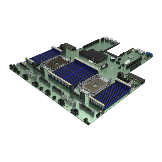
Intel M50CYP2SB Series Technical Specification (160 pages)
Server Board
Brand:
Intel
| Category:
Computer Hardware
| Size: 12.21 MB
Table of Contents
Table of Contents
5
Introduction
13
Figure 1. Intel® Server Board M50CYP2SB Family
13
Reference Documents
14
Table 1. Intel® Server M50CYP Family Reference Documents and Support Collaterals
14
Server Board Family Overview
16
Server Board Feature Set
16
Table 2. Intel® Server Board M50CYP2SB Family Features
16
Server Board Component / Feature Identification
19
Figure 2. Intel® Server Board M50CYP2SBSTD Component / Feature Identification
19
Figure 3. Intel® Server Board M50CYP2SB1U Component / Feature Identification
20
Figure 4. Intel® Light-Guided Diagnostics - LED Identification
21
Figure 5. Fan Fault Leds on Intel® Server Board M50CYP2SB1U
22
Figure 6. Intel® Light-Guided Diagnostics - DIMM Fault Leds
22
Figure 7. System Configuration and Recovery Jumpers
23
Server Board Dimensions
24
Figure 8. Intel® Server Board M50CYP2SBSTD and M50CYP2SB1U Board Dimensions
24
Server Board Mechanical Drawings
25
Figure 9. Intel® Server Board M50CYP2SB Family Top Surfaces Keep out Zone (Drawing 1)
25
Figure 10. Intel® Server Board M50CYP2SB Family Top Surface Keep out Zone (Drawing 2)
26
Figure 11. Intel® Server Board M50CYP2SB Family Bottom Surface Keep out Zone (Drawing 1)
27
Figure 12. Intel® Server Board M50CYP2SB Family Bottom Surface Keep out Zone (Drawing 2)
28
Figure 13. Intel® Server Board M50CYP2SB Family Components Position (Drawing 1)
29
Figure 14. Intel® Server Board M50CYP2SB Family Components Position (Drawing 2)
30
Figure 15. Intel® Server Board M50CYP2SB Family Holes Position
31
Server Board Architecture Overview
32
Figure 16. Intel® Server Board M50CYP2SBSTD Architectural Block Diagram
32
Figure 17. Intel® Server Board M50CYP2SB1U Architectural Block Diagram
33
Processor Support
34
Processor Cooling Overview
34
Figure 18. PHM Components and Processor Socket Reference Diagram
34
Processor Cooling Requirements
35
Processor Thermal Design Power (TDP) Support
35
Processor Family Overview
36
Figure 19. 3 Rd Gen Intel® Xeon® Scalable Processor Identification
36
Supported Technologies
37
Table 3. 3 Rd Gen Intel® Xeon® Scalable Processor Family Feature Comparison
37
Processor Population Rules
38
Memory Support
39
Memory Subsystem Architecture
39
Supported Memory
39
Figure 20. Memory Slot Connectivity
39
Standard DDR4 DIMM Support
40
Figure 21. Standard SDRAM DDR4 DIMM Module
40
Table 4. Supported DDR4 DIMM Memory
40
Intel® Optane™ Persistent Memory 200 Series Module Support
41
Figure 22. Intel® Optane™ Persistent Memory 200 Series Module
41
Table 5. Maximum Supported Standard SDRAM DIMM Speeds by Processor Shelf
41
Figure 23. <F2> BIOS Setup Screen Navigation for Intel® Optane™ Pmem Setup Options
42
Memory Population
43
Figure 24. Intel® Optane™ Pmem Configuration Menu in <F2> BIOS Setup
43
Figure 25. Server Board Memory Slot Layout
43
DDR4 DIMM Population Rules
44
Table 6. DDR4 DIMM Attributes Table for "Identical" and "Like" Dimms
44
Intel® Optane™ Persistent Memory 200 Series Module Rules
45
Table 7. Intel® Optane™ Persistent Memory 200 Series Module Support
46
Table 8. Standard DDR4 Dimms Compatible with Intel® Optane™ Persistent Memory 200 Series Module
46
Recommended Memory Configurations
47
Figure 26. Memory Slot Identification
47
Table 9. Standard DDR4 DIMM-Only Per Socket Population Configurations
47
Memory RAS Support
48
Table 10. Standard DDR4 DIMM and Intel® Optane™ Persistent Memory 200 Series Module (Pmem) Population Configurations
48
Table 11. Memory RAS Features
49
Table 12. Intel® Optane™ Persistent Memory 200 Series RAS Features
50
Table 13. Compatibility of RAS Features Intel® SGX, Intel® TME, and Intel® TME-MT
51
Server Management
52
Remote Management Port
52
Figure 27. Remote Management Port
52
Configuring System Management Port Using <F2> BIOS Setup
53
Figure 28. BIOS Setup BMC LAN Configuration Screen
53
Standard System Management Features
54
Virtual KVM over HTML5
54
Figure 29. BIOS Setup User Configuration Screen
54
Integrated Baseboard Management Controller Web Console (Integrated BMC Web Console)
55
Figure 30. Integrated BMC Web Console Login Page
55
Redfish* Support
56
IPMI 2.0 Support
56
Out-Of-Band BIOS / BMC Update and Configuration
56
System Inventory
56
Figure 31. Integrated BMC Web Console - Main Console View
56
Autonomous Debug Log
57
Security Features
57
Advanced System Management Features
57
Virtual Media Image Redirection (HTML5 and Java)
57
Virtual Media over Network Share and Local Folder
58
Active Directory Support
58
Intel® Data Center Manager (DCM) Support
58
Server Board Connector / Header Pinout Definition
59
Power Connectors
59
Main Power Connectors
59
Figure 32. "MAIN PWR 1" and "MAIN PWR 2" Connectors
59
Table 14. Main Power (Slot 1) and Main Power (Slot 2) Connector Pinout ("MAIN PWR 1" and "MAIN PWR 2")
60
Hot Swap Backplane (HSBP) Power Connector
61
Figure 33. Hot Swap Backplane Power Connector
61
Table 15. Hot Swap Backplane Power Connector Pinout ("HSBP PWR")
61
Optional 12-V Power Connectors
62
Figure 34. Riser Slot Auxiliary Power Connectors
62
Table 16. Riser Slot Auxiliary Power Connector Pinout
62
Peripheral Power Connector
63
Figure 35. Peripheral Power Connector
63
Table 17. Peripheral Drive Power Connector Pinout
63
Front USB 3.0/2.0 Panel Header and Front Control Panel Header
64
Front USB 3.0/2.0 Panel Header
64
Figure 36. Front Panel Header and Front Control Panel Header
64
Table 18. Front USB 3.0/2.0 Panel Header Pinout
64
Front Control Panel Header Pinout
65
Serial Port B Header
65
Figure 37. Serial Port B Header (Internal)
65
Table 19. Front Control Panel Header Pinout
65
I 2 C Connectors
66
Figure 38. I
66
Table 20. Serial Port B Header Pinout
66
Table 21. I
66
Fan Connectors
67
System Fan Connectors
67
Figure 39. 8-Pin Fan Connector - Intel® Server Board M50CYP2SBSTD and M50CYP2SB1U
67
Figure 40. 6-Pin Fan Connector - Intel® Server Board M50CYP2SBSTD
67
Table 22. 8-Pin Fan Connector Pinout - Intel® Server Board M50CYP2SBSTD and M50CYP2SB1U
67
CPU Fan Connectors
68
Pcie* Slimsas* Connector
68
Figure 41. CPU 0 / CPU 1 Fan Connectors
68
Figure 42. Pcie* Slimsas* Connectors
68
Table 23. 6-Pin Fan Pinout - Intel® Server Board M50CYP2SBSTD
68
Table 24. CPU 0 / CPU 1 Fan Pinout
68
Table 25. Pcie* Slimsas* Connector a Pinout (CPU 0 and CPU 1)
69
Table 26. Pcie* Slimsas* Connector B Pinout (CPU 0 and CPU 1)
70
Table 27. Pcie* Slimsas* Connector C Pinout (CPU 0 and CPU 1)
71
Table 28. Pcie* Slimsas* Connector D Pinout (CPU 0 and CPU 1)
72
PCI Express (Pcie*) Support
73
Pcie* Enumeration and Allocation
73
Table 29. Processor / Chipset Pcie* Port Routing
73
Pcie* Riser Card Support
74
Pcie* Interposer Riser Slot (Intel® Server Board M50CYP2SB1U Only)
74
Figure 43. Pcie* Interposer Riser Card
74
Table 30. Pcie* Interposer Riser Card Connector Description
74
Table 31. Pcie* Interposer Riser Slot Pinout
74
Pcie* Interposer Riser Card Usage in an Intel® Server System M50CYP1UR Family
75
Figure 44. Pcie* Nvme* Riser Card for Riser Slot #2
75
Figure 45. Pcie* Interposer Riser Card to Pcie* Nvme* Riser Card Connectivity
76
Table 32. Pcie* Nvme* Riser Card Connector Description
76
Storage Support
77
Server Board SATA Support
77
Table 33. SATA and Ssata Controller Feature Support
77
SATA Support through Mini-SAS HD Connectors
78
SATA Support through M.2 Connectors
78
Staggered Disk Spin-Up
78
Figure 46. SATA Ports on Server Board
78
Intel® Virtual RAID on Chip (Intel® VROC) for SATA
79
Figure 47. BIOS Setup Mass Storage Controller Configuration Screen
79
M.2 SSD Storage Support
80
Figure 48. M.2 Module Connector Location
80
Nvme* Storage Support
81
Pcie* Slimsas* Support
81
Figure 49. Pcie* Slimsas* Connectors
81
Table 34. CPU to Pcie* Nvme* Slimsas* Connector Routing
81
Intel® Volume Management Device (Intel® VMD) 2.0 for Nvme
82
Figure 50. Nvme* Storage Bus Event / Error Handling
82
Intel® Virtual RAID on Chip (Intel® VROC) for Nvme
83
Table 35. CPU to Pcie* Nvme* Slimsas* Connector Routing
83
Figure 51. Intel® VROC 7.5 Key Insertion
84
Table 36. Optional VROC 7.5 Upgrade Key - Supported Nvme* RAID Features
84
System I/O
85
Serial Port Support
85
Figure 52. Serial Port a
85
Figure 53. RJ45 Serial Port a Pin Orientation
85
Figure 54. J19 Jumper Header for Serial Port a Pin 7 Configuration
86
Table 37. RJ45 Serial Port a Connector Pinout
86
USB Support
87
Figure 55. External USB 3.0 Connector Ports
87
Table 38. USB 3.0 Single Stack Rear Connector Pinout
87
Internal USB 2.0 Type-A Connector
88
Figure 56. Internal USB 2.0 Type-A Connector
88
Table 39. Internal USB 2.0 Type-A Connector Pinout
88
Video Support
89
Video Resolutions
89
Server Board Video and Add-In Video Adapter Support
89
Table 40. Supported Video Resolutions
89
Dual Monitor Support
90
Intel® Ethernet Network Adapter for OCP* Support
90
Figure 57. Intel® Ethernet Network Adapter for OCP* Placement
90
Table 41. Supported Intel® Ethernet Network Adapters for OCP
90
10. Intel® Light Guided Diagnostics
91
Figure 58. Intel® Light-Guided Diagnostics - LED Identification
91
10.1 Post Code Diagnostic Leds
92
10.2 System ID LED
92
10.3 System Status LED
92
Figure 59. Exploded View of POST Code Diagnostic, System ID, and System Status LED Area
92
Table 42. System Status LED State Definitions
93
10.4 BMC Boot / Reset Status LED Indicators
94
Table 43. BMC Boot / Reset Status LED Indicators
94
10.5 Processor Fault Leds
95
10.6 Memory Fault Leds
95
Figure 60. Memory Fault LED Location
95
10.7 Fan Fault Leds
96
Figure 61. Fan Fault Leds (Intel® Server Board M50CYP2SBSTD Shown)
96
11. System Software Stack
97
11.1 Hot Keys Supported During POST
98
POST Logo/Diagnostic Screen
98
BIOS Boot Pop-Up Menu
98
Table 44. POST Hot Keys
98
Entering BIOS Setup
99
BIOS Update Capability
99
11.2 Field Replaceable Unit (FRU) and Sensor Data Record (SDR) Data
99
Loading FRU and SDR Data
99
12. System Security
100
12.1 Password Protection
100
Figure 62. BIOS Setup Security Tab
100
Password Setup
101
System Administrator Password Rights
101
Authorized System User Password Rights and Restrictions
102
12.2 Front Panel Lockout
102
Intel® Platform Firmware Resilience (Intel® PFR)
102
Intel® Total Memory Encryption (Intel® TME)
103
Intel Software Guard Extensions (Intel SGX)
103
12.6 Trusted Platform Module (TPM) Support
104
Trusted Platform Module (TPM) Security BIOS
105
Physical Presence
105
TPM Security Setup Options
105
Intel® Cbnt - Converged Intel® Boot Guard and Trusted Execution Technology (Intel® TXT)
106
12.8 Unified Extensible Firmware Interface (UEFI) Secure Boot Technology
106
13. Server Board Configuration and Service Jumpers
107
BIOS Default Jumper (BIOS DFLT - J70)
107
Figure 63. Reset and Recovery Jumper Header Locations
107
Password Clear Jumper (PASSWD_CLR - J29)
108
Intel® Management Engine (Intel® ME) Firmware Force Update Jumper (ME_FRC_UPDT - J22)
108
BMC Force Update Jumper (BMC FRC UPD - J20)
109
BIOS SVN Downgrade Jumper (BIOS_SVN_DG - J71)
110
BMC SVN Downgrade Switch (BMC_SVN_DG - S5)
111
Appendix A. Getting Help
112
Appendix B. Integration and Usage Tips
113
Appendix C. Post Code Diagnostic LED Decoder
114
Figure 64. Server Board POST Diagnostic Leds
114
Early POST Memory Initialization MRC Diagnostic Codes
115
Table 45. POST Progress Code LED Example
115
Table 46. Memory Reference Code (MRC) Progress Codes
115
Table 47. Memory Reference Code (MRC) Fatal Error Codes
116
BIOS POST Progress Codes
117
Table 48. POST Progress Codes
117
Appendix D. Post Code Errors
120
Table 49. POST Error Messages and Handling
121
D.1 POST Error Beep Codes
126
Table 50. POST Error Beep Codes
126
Table 51. Integrated BMC Beep Codes
126
D.2 Processor Initialization Error Summary
127
Table 52. Mixed Processor Configurations Error Summary
127
Appendix E. Statement of Volatility
129
Table 53. Server Board Components
129
Appendix F. Connectors and Headers
130
Table 54. Connectors and Headers
130
Appendix G. Sensors
131
Figure 65. Server Board Sensor Map
131
Table 55. Available Sensors Monitored by the BMC
132
Appendix H. Server Board Installation and Component Replacement
134
H.1 Server Board Installation Guidelines
135
Figure 66. Server Board Mounting Hole Locations
135
Figure 67. Possible Server Board Mounting Options
136
Table 56. Server Board Mounting Screw Torque Requirements
136
Figure 68. Server Board Rear I/O Connectors
137
Figure 69. Rear I/O Shield Placement
137
H.2 Processor Replacement Instructions
138
H.2.1 Processor Heat Sink Module (PHM) and Processor Removal
139
Figure 70. Processor Heat Sink Handling
139
Figure 71. PHM Assembly Removal from Processor Socket
139
Figure 72. Reinstall the Socket Cover
140
Figure 73. Processor Removal from PHM Assembly
140
PHM and Processor Installation
141
Processor Heat Sink Module (PHM) Assembly
141
Figure 74. Processor Carrier Clip Removal from PHM Assembly
141
Figure 75. Installing Processor Carrier Clip Onto Processor - Part 1
141
Figure 76. Installing Processor Carrier Clip Onto Processor - Part 2
142
Figure 77. Removing Heat Sink from Its Packaging
142
Figure 78. Processor Heat Sink Anti-Tilt Wires in the Outward Position
143
Figure 79. Pin 1 Indicator of Processor Carrier Clip
143
Processor Installation
144
Figure 80. Socket Protective Cover Removal
144
Figure 81. PHM Alignment with Socket Assembly
144
Figure 82. PHM Installation Onto Server Board
145
Figure 83. Tighten Heat Sink Fasteners
145
H.3 DIMM / Intel® Optane™ Pmem Replacement Instructions
146
Figure 84. Memory Module Removal
146
Figure 85. DIMM Installation
146
Appendix I. Supported Intel® Server Systems
148
Intel® Server System M50CYP2UR Family
148
Figure 86. Intel® Server System M50CYP2UR Family
148
Table 57. Intel® Server System M50CYP2UR Family Features
148
Intel® Server System M50CYP1UR Family
152
Figure 87. Intel® Server System M50CYP1UR Family
152
Table 58. Intel® Server System M50CYP1UR Family Features
152
Appendix J. Regulatory Information
156
Appendix K. Glossary
158
Advertisement
Advertisement
Related Products
Intel MFS5000SI - Multi-Flex Server Compute Module
Intel MFS5520VI - Multi-Flex Server Compute Module
Intel MultiProcessor
Intel EtherExpress PRO/100 MBLA1656
Intel EtherExpress PRO/100 MBLA1600
Intel Management Module
Intel MCS48
Intel MX4305UE
Intel Pentium mPGA478
Intel Mobileye EyeCAN Kit
Intel Categories
Motherboard
Computer Hardware
Server
Server Board
Desktop
More Intel Manuals
Login
Sign In
OR
Sign in with Facebook
Sign in with Google
Upload manual
Upload from disk
Upload from URL