
Related Manuals for Intel MX4305UE


Summary of Contents for Intel MX4305UE
- Page 1 MX4305UE 8th Gen Intel® Whiskey Lake 4305UE Processor Onboard User’s Manual Ver. 0.1...
-
Page 2: Table Of Contents
1.6.4 ATX power connectors (ATX12V1, 4pin) ....................29 1.6.5 Serial Port connectors (COM1~4) ......................29 1.6.6 Serial ATA Connector (SATA1 ) ......................30 1.6.7 USB connectors (USB78) ........................30 1.6.8 USB connectors (USB56) ........................31 1.6.9 SATA power connector (SATAPW1) ..................... 32 2 MX4305UE User’s Manual... - Page 3 2.4.6.1.1 Smart FAN mode Configuration ......................53 2.4.7 S5 RTC wake settings ..........................56 2.4.8 Serial Port Console Redirection ......................57 2.4.9 Intel TXT information ..........................57 2.4.10 USB Configuration ..........................59 2.4.11 Compatibility Support Module Configuration ..................60 2.4.12 NVMe Configuration ..........................61 2.4.13 SDIO Configuration ..........................
- Page 4 2.5.2.5 Serial IO Configuration ..........................76 2.5.2.5.1 Serial IO I2C0 Settings ......................... 77 2.6 Security ................................78 2.6.1 Secure boot ............................79 2.6.1.1 Key management ..........................80 2.7 Boot ................................81 2.8 Save & Exit ..............................82 4 MX4305UE User’s Manual...
-
Page 5: Safety Information
If you encounter technical problems with the product, contact a qualified service technician or your retailer. The symbol of the crossed out wheeled bin indicates that the product (Electrical and electronic equipment) should not be placed in municipal waste. Check local regulations for disposal of electronic products. MX4305UE User’s Manual 5... - Page 6 This device complies with the requirements in Part 15 of the FCC rules. Operation is subject to the following two conditions: This device may not cause harmful interference. This device must accept any interference received, including interference that may cause undesired operation. 6 MX4305UE User’s Manual...
-
Page 7: About This Guide
CAUTION: Information to prevent damage to the components when trying to complete a task. IMPORTANT: Instructions that you MUST follow to complete a task. NOTE: Tips and additional information to help you complete a task. MX4305UE User’s Manual 7... -
Page 8: Typography
Example: <Ctrl>+<Alt>+<D> Command Means that you must type the command exactly as shown, then supply the required item or value enclosed in brackets Example: At the DOS prompt, type the command line: afudos /i[filename] afudos /iP5P800VM.ROM 8 MX4305UE User’s Manual... -
Page 9: Packing List
MX4305UE User’s Manual Packing List Before you begin installing your single board, please make sure that the following materials have been shipped: 1 x MX4305UE Mini-ITX Main board 1x SATA power cable 1 x I/O Shield (high profile) ... -
Page 10: Revision History
MX4305UE User’s Manual Revision History Revision Revision History Date V 0.1 First release version Nov. 2019 10 MX4305UE User’s Manual... -
Page 11: Specifications Summary
MX4305UE User’s Manual Specifications Summary Specifications System Intel® Whiskey Lake; Scalable across i7, i5, i3, Pentium Gold, and Celeron Processor Two 260-pin So-DIMM DDR4 2400Mhz, up to 32GB Max (Horizontal Type) Memory PCI-E Up to 16 PCIe x1 Gen3 Lanes Available Up to 6 x USB 3.1 Gen 2 Port Available... - Page 12 1 x SATA III Connectors (Red) 1 x 15 pin SATA Power Connector 1 x Front Audio Header (2.54mm Pitch) 1 x Front Panel Header with Shroud (2.54mm Pitch) 1 x Amplifier Locking Type Header (2.00mm Pitch) 1 x Onboard Buzzer 1 x Horizontal Socket Type Battery 1 x Mini‐Fit Jr 4 Pin DC‐In Connector Power Power & Connector 12V~24V DC-In Mechanical & Environmental Operating Temperature 0~60°C (32~140°F) Operating Humidity 5% to 85% non-condensing Size (L x W) 6.7 inch x 6.7 inch 12 MX4305UE User’s Manual...
- Page 13 MX4305UE User’s Manual Block Diagram MX4305UE User’s Manual 13...
-
Page 14: Chapter 1 - Product Introduction
MX4305UE User’s Manual This chapter describes the motherboard features and the new technologies it supports. Product Introduction 14 MX4305UE User’s Manual... -
Page 15: Before You Proceed
The edge with external ports goes to the rear part of the chassis as indicated in the image below. 1.2.2 Screw Holes Place eight (8) screws into the holes indicated by circles to secure the motherboard to the chassis. Do not over tighten the screws! Doing so can damage the motherboard. MX4305UE User’s Manual 15... -
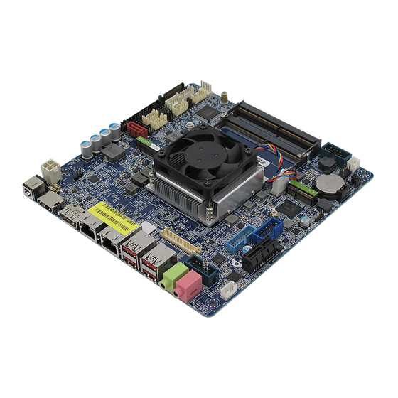
Page 16: Motherboard Layout
MX4305UE User’s Manual Place this side towards the rear of the chassis. 1.2.3 Motherboard Layout 16 MX4305UE User’s Manual... -
Page 17: Layout Content List
4 x 1 wafer, pitch 2.54mm F_PANEL1 Intel Front Panel connector 5 x 2 header, pitch 2.54mm ATX12V1 12V ATX power connectors 2 x 2 wafer COM1 ~ 4 Serial Port Connector 5 x 2 header, pitch 2.00mm MX4305UE User’s Manual 17... -
Page 18: System Memory
(SDRAM) with a high bandwidth ("double data rate") interface. The primary advantages of DDR4 over its predecessor, DDR3, include higher module density and lower voltage requirements, coupled with higher data rate transfer speeds. DDR4 SODIMM sockets 18 MX4305UE User’s Manual... -
Page 19: Installing A Dimm
A DDR4 SODIMM is keyed with a notch so that it fits in only one direction. DO NOT force a SODIMM into a socket to avoid damaging the DIMM. The DDR4 SODIMM sockets do not support DDR3 SODIMMs. DO NOT install DDR3 SODIMMs to the DDR4 SODIMM socket. MX4305UE User’s Manual 19... -
Page 20: Removing A Ddr4 Dimm
1. Press the two ejector tabs on the slot outward simultaneously, and then pull out the DIMM module. Support the DIMM lightly with your fingers when pressing the ejector tabs. The DIMM might get damaged when it flips out with extra force. 20 MX4305UE User’s Manual... -
Page 21: Expansion Card
2. Assign an IRQ to the card if needed. Refer to the tables on the next page. 3. Install the software drivers for the expansion card. 1.4.3 PCI Express x1 slot This motherboard supports one PCI Express x1 slot that complies with the PCI Express specifications. MX4305UE User’s Manual 21... -
Page 22: Connector
MX4305UE User’s Manual 1.4.4 M.2 connector Support PCIe and SATA interface of this connector. 22 MX4305UE User’s Manual... -
Page 23: Jumpers
You do not need to clear the RTC when the system hangs due to overclocking. For system failure due to overclocking, use the C.P.R. (CPU Parameter Recall) feature. Shut down and reboot the system so the BIOS can automatically reset parameter settings to default values. MX4305UE User’s Manual 23... -
Page 24: At/Atx Power Mode Select (Jpson1)
MX4305UE User’s Manual 1.5.2 AT/ATX Power Mode Select (JPSON1) This jumper allows you to select ATX Mode or AT mode 1.5.3 COM POWER SETTING (JCOMPWR1~2) This jumper allows you to select COM1/COM2 to support Ring/+12V/+5V Ring (Default) +12V 24 MX4305UE User’s Manual... -
Page 25: Lvds Panel Voltage Selection (Jbklvol1)
MX4305UE User’s Manual 1.5.4 LVDS panel voltage Selection (JBKLVOL1) 1.5.5 Brightness control mode Selection: (JLVDS_BKL1) MX4305UE User’s Manual 25... -
Page 26: Connectors
Status Description No link 10Mbps connection Orange Linked Green 100Mbps connection Blinking Data Orange 1Gbps activity connection USB1,2 USB 3.1 Gen2 These one Universal Serial Bus (USB) ports are Connectors available for connecting USB 3.1 devices. 26 MX4305UE User’s Manual... -
Page 27: Cpu And System Fan Connectors (Cpu_Fan1, Sys_Fan1)
Do not forget to connect the fan cables to the fan connectors. Insufficient air flow inside the system may damage the motherboard components. These are not jumpers! DO NOT place jumper caps on the fan connectors. MX4305UE User’s Manual 27... -
Page 28: System Panel (F_Panel1)
Hard Disk Drive Activity LED (Pin 1-3) This 2-pin connector is for the HDD Activity LED. Connect the HDD Activity LED cable to this connector. The IDE LED lights up or flashes when data is read from or written to the HDD. 28 MX4305UE User’s Manual... -
Page 29: Atx Power Connectors (Atx12V1, 4Pin)
1.6.5 Serial Port connectors (COM1~4) This connector is for a serial (COM) port. Connect the serial port module cable to this connector, and then install the module to a slot opening at the back of the system chassis. MX4305UE User’s Manual 29... -
Page 30: Serial Ata Connector (Sata1 )
These connectors are for USB 2.0 ports. Connect the optional USB module cable to any of these connectors, and then install the module to a slot opening at the back of the system chassis. These USB connectors comply with USB 2.0 specification that supports up to 480 Mbps connection speed. 30 MX4305UE User’s Manual... -
Page 31: Usb Connectors (Usb56)
19. +5V 2. USB3_RX- 18. USB3_RX- 3. USB3_RX+ 17. USB3_RX+ 4. GND 16. GND 5. USB3_TX- 15. USB3_TX- 6. USB3_TX+ 7. GND 14. USB3_TX+ 8. USB- 13. GND 9. USB+ 12. USB- 10. NC 11. USB+ MX4305UE User’s Manual 31... -
Page 32: Sata Power Connector (Satapw1)
17. LVDS_A3- 18. LVDS_A2- 15. LVDS_A3+ 16. LVDS_A2+ 13. GND 14. GND 11. LVDS_A1- 12. LVDS_A0- 9. LVDS_A1+ 10. LVDS_A0+ 7. GND 8. GND 5. DDC_CLK 6. DDC_DATA 3. VDD_+3.3V 4. VDD_+5V 1. VDD_+3.3V 2. VDD_+5V 32 MX4305UE User’s Manual... -
Page 33: Bit Gpio Header (Jdio1)
This connector is for a chassis-mounted front panel audio I/O module that supports either HD Audio or legacy AC ‘97 (optional) audio standard. 10. LINE2-JD 9. LINE2L 8. NC 7. SENSEB 6. MIC2-JD 5. LINE2R 4. NC 3. MIC2R 2. GND 1. MIC2L MX4305UE User’s Manual 33... -
Page 34: Amplifier Connector (Jamp1)
MX4305UE User’s Manual 1.6.13 Amplifier Connector (JAMP1) 1.6.14 SM bus connector (JSMB1) 34 MX4305UE User’s Manual... -
Page 35: Lvds Panel Backlight Connector (Jbkl1)
MX4305UE User’s Manual 1.6.15 LVDS panel backlight connector (JBKL1) 1.6.16 Chassis Intrusion Connector (JCASE1) MX4305UE User’s Manual 35... -
Page 36: I2C Connector (I2C1)
MX4305UE User’s Manual 1.6.17 I2C connector (I2C1) 36 MX4305UE User’s Manual... - Page 37 MX4305UE User’s Manual This chapter tells how to change the system settings through the BIOS Setup menus. Detailed descriptions of the BIOS parameters are also provided. BIOS Step MX4305UE User’s Manual 37...
-
Page 38: Chapter 2 - Bios Setup
The BIOS setup screens shown in this section are for reference purposes only, and may not exactly match what you see on your screen. Visit the system builder’s website to download the latest BIOS file for this motherboard 38 MX4305UE User’s Manual... -
Page 39: Legend Box
<F3> to load the optimal default values. While moving around through the Setup program, note that explanations appear in the Item Specific Help window located to the right of each menu. This window displays the help text for the currently highlighted field. MX4305UE User’s Manual 39... -
Page 40: Bios Menu Screen
To access the menu items, press the up/down/right/left arrow key on the keyboard until the desired item is highlighted, then press [Enter] to open the specific menu. 40 MX4305UE User’s Manual... -
Page 41: Main Setup
Use this menu for basic system configurations, such as time, date etc. BIOS Information Displays the auto-detected BIOS information. System Date The date format is <Date>,<Month>,<Day>,<Year>. System Time The time format is <Hour>,<Minute>,<Second>. MX4305UE User’s Manual 41... -
Page 42: Advanced Bios Setup
The Advanced BIOS Setup screen is shown below. The sub menus are described on the following pages. Take caution when changing the settings of the Advanced menu items. Incorrect field values can cause the system to malfunction. 42 MX4305UE User’s Manual... -
Page 43: Cpu Configuration
Configuration options:[No change in owner EPOCHs][change to new random owner EPOCHs][Manual user defined owner EPOCHs] Intel Virtualization Technology [Enabled] When enabled, a VWM can utilize the additional hardware capabilities provided by vandrpool Technology Configuration options: [Disabled][Enabled] MX4305UE User’s Manual 43... - Page 44 Number of Cores to enable in each processor package Configuration options: [all] [1][2][3] This depends on CPU sku. Hyper-Threading [Enabled] Enabled or Disabled the hyper threading of Intel CPU Configuration options: [Disabled][Enabled] This depends on CPU sku. Intel Trusted Execution Technology [Disabled] Enabled or Disabled Intel Trusted Execution Technology.
-
Page 45: Pch-Fw Configuration
2.4.2 PCH-FW Configuration It shows ME version and ME status. ME State [Enable] Enable or Disable Intel ME. Configuration options: [Enable] [Disable] ME Unlock Control [Lock] ME unlock switch function. This function will automatically recover setting from Unlock to Lock after power-on system. - Page 46 Enable or Disable SHA-1 PCR Bank. Configuration options: [Enable] [Disable] SHA256 PCR Bank [Enable] Enable or Disable SHA256 PCR Bank. Configuration options: [Enable] [Disable] Pending Operation [None] Schedule and operation for the Security Device. Configuration options: [None] [TPM clear] 46 MX4305UE User’s Manual...
-
Page 47: Acpi Settings
Configuration options: [Suspend Disabled] [S3 only(suspend to RAM )] S3 Video Repost [Disabled] Enable or disable S3 video repost Configuration options: [Disabled] [Enabled] PCIE# wake from S5 [Disabled] Enable or disable PCIE wake the system from S5. Configuration options: [Disabled] [Enabled] MX4305UE User’s Manual 47... -
Page 48: Nct6106D Super Io Configuration
Fill watchdog timeout value, 0 means disables Chassis opened warning [Disabled] Select chassis intrusion enabled to Disabled Configuration options: [Disabled] [Enabled] ErP/EuP S5 support [Disabled] ErP/EuP S5 support mode Selection Configuration options: [Disabled] [Enabled] 48 MX4305UE User’s Manual... -
Page 49: Serial Port 1 Configuration
Enable or Disable serial Port (COM) Configuration options: [Disabled] [Enabled] Change Settings [Auto] Select an optimal settings for super IO device Configuration options: as below COM mode Select [RS232] Configure the Com port mode Configuration options: as below MX4305UE User’s Manual 49... -
Page 50: Serial Port 2 Configuration
Configuration options: [Disabled] [Enabled] Change Settings [Auto] Select an optimal settings for super IO device Configuration options: as below 2.4.5.3 Serial Port 3 Configuration Serial Port [Enabled] Enable or Disable serial Port (COM) Configuration options: [Disabled] [Enabled] 50 MX4305UE User’s Manual... -
Page 51: Serial Port 4 Configuration
Configuration options: as below 2.4.5.4 Serial Port 4 Configuration Serial Port [Enabled] Enable or Disable serial Port (COM) Configuration options: [Disabled] [Enabled] Change Settings [Auto] Select an optimal settings for super IO device Configuration options: as below MX4305UE User’s Manual 51... -
Page 52: Nct6106D Hw Monitor
MX4305UE User’s Manual 2.4.6 NCT6106D HW monitor Display Hardware monitor information 2.4.6.1 Smart FAN 52 MX4305UE User’s Manual... -
Page 53: Smart Fan Mode Configuration
Configuration options: [Enabled] [Disabled] [Manual] 2.4.6.1.1 Smart FAN mode Configuration Setting different FAN on this motherboard when enable the Smart Fan Function. SYS_FAN1 Smart Fan Target [Disabled] Smart FAN target temperature Configuration options: Please see below picture MX4305UE User’s Manual 53... - Page 54 MX4305UE User’s Manual SYS_FAN1 Min.FAN Speed(62.5%) Smart FAN minimum settings Configuration options: Please see below picture CPU_FAN1 Smart Fan Target [Disabled] Smart FAN target temperature Configuration options: Please see below picture 54 MX4305UE User’s Manual...
- Page 55 MX4305UE User’s Manual CPU_FAN1 Min.FAN Speed(62.5%) Smart FAN minimum settings Configuration options: Please see below picture MX4305UE User’s Manual 55...
-
Page 56: S5 Rtc Wake Settings
MX4305UE User’s Manual 2.4.7 S5 RTC wake settings Wake system from S5 [Disabled] Enabled or Disabled system wake on alarm event Configuration options: [Enabled] [Disabled] 56 MX4305UE User’s Manual... -
Page 57: Serial Port Console Redirection
MX4305UE User’s Manual 2.4.8 Serial Port Console Redirection Console Redirection [Disabled] Enabled or Disabled Console Redirection Configuration options: [Enabled] [Disabled] 2.4.9 Intel TXT information Display Intel TXT information MX4305UE User’s Manual 57... - Page 58 MX4305UE User’s Manual 58 MX4305UE User’s Manual...
-
Page 59: Usb Configuration
This is a workaround for OSes without XHCI hand-off support. This XHCI ownership change should be claimed by XHCI drivers Configuration options: [Disabled] [Enabled] USB Mass storage Driver Support[Enabled] Enabled or Disabled USB Mass storage driver support. Configuration options: [Disabled] [Enabled] MX4305UE User’s Manual 59... -
Page 60: Compatibility Support Module Configuration
Control the execution of UEFI and Legacy Video OpROM Configuration options: [Do not launch] [UEFI][Legacy] Other PCI devices [UEFI] Determines OpROM execution policy for devices other than Network, Storage, or Video. Configuration options: [Do not launch] [UEFI][Legacy] 60 MX4305UE User’s Manual... -
Page 61: Nvme Configuration
MX4305UE User’s Manual 2.4.12 NVMe Configuration Display NVMe controller or Drive information 2.4.13 SDIO Configuration Display SDIO information MX4305UE User’s Manual 61... - Page 62 MX4305UE User’s Manual SDIO Access Mode [Auto] SDIO Access Mode Selection Configuration options: [Auto] [ADMA] [SDMA] [PIO] MMC – BJTD4R (31.2GB) [Auto] Mass Storage Device Emulation Type Configuration options: [Auto] [Floppy][Forced FDD][Hard Disk] 62 MX4305UE User’s Manual...
-
Page 63: Network Stack Configuration
Enabled IPv6 PXE boot support Configuration options: [Disabled] [Enabled] PXE boot wait time Wait time to press ESC to abort the PXE boot Media Detect Count Number of times presence of media will be checked MX4305UE User’s Manual 63... -
Page 64: Chipset
MX4305UE User’s Manual 2.5 Chipset 64 MX4305UE User’s Manual... -
Page 65: System Agent (Sa) Configuration
MX4305UE User’s Manual 2.5.1 System Agent (SA) Configuration VT-d [Enabled] VT-d capability Configuration options: [Disabled] [Enabled] 2.5.1.1 Memory configuration Display memeory information MX4305UE User’s Manual 65... -
Page 66: Graphic Configuration
Max TOLUD [Dynamic] Maximum value of TOLUD. Configuration options: As above picture 2.5.1.2 Graphic Configuration Graphic configuration settings Primary Display[Auto] Select which of IGFX/PEG/PCI graphic device should be primary display or select SG for 66 MX4305UE User’s Manual... - Page 67 PSMI Region Size [32MB] Enable or disable PSMI Configuration options: As below picture DVMT Pre-Allocated [32M] Select DVMT 5.0 Pre-allocated (Fixed) Graphics memory size used by the internal graphics device. Configuration options: As below picture MX4305UE User’s Manual 67...
-
Page 68: Lcd Control
Select DVMT 5.0 Total graphic memory size used by the internal graphic device Configuration options: [128M][256M][Max] 2.5.1.3 LCD Control LVDS Control [Disable] Configuration options: [Enabled][Disabled] If choosing [Enable], it is shown as below picture : 68 MX4305UE User’s Manual... - Page 69 MX4305UE User’s Manual a. LVDS Panel Type Configuration options : As below picture b. LCD Brightness Control Configuration Option: [DC Control][PWM Control] c. LVDS Brightness Control : Adjust Brightness of LVDS from 1 to 255 MX4305UE User’s Manual 69...
-
Page 70: Pch-Io Configuration
Enable or Disable boot option for Lan2 Controller Configuration options: [Disabled][Enabled] Restore AC power Loss [Power off] Specify what state to go to when power is re-applied after a power failure. Configuration options: [Power on][Power off][Last State] 70 MX4305UE User’s Manual... -
Page 71: Pci Express Configuration
Set the ASPM level: Force L0s- Force all links to L0s State; Auto- BIOS auto configure; Disabled- Disables ASPM Configuration options: [Disabled][L0s][L1][L0sL1][Auto] PCIe Speed [Auto] Select PCI Express Port speed Configuration options: [Auto][Gen1][Gen2][Gen3] Detect Non-Compliance Device [Disable] Configuration options: [Disable][Enable] MX4305UE User’s Manual 71... -
Page 72: Pci Express Root Port 9(M.2)(Key M)
Set the ASPM level: Force L0s- Force all links to L0s State; Auto- BIOS auto configure; Disabled- Disables ASPM Configuration options: [Disabled][L0s][L1][L0sL1][Auto] PCIe Speed [Auto] Select PCI Express Port speed Configuration options: [Auto][Gen1][Gen2][Gen3] Detect Non-Compliance Device [Disable] Configuration options: [Disable][Enable] 72 MX4305UE User’s Manual... -
Page 73: Pci Express Root Port 14(M.2)(Key E)
Set the ASPM level: Force L0s- Force all links to L0s State; Auto- BIOS auto configure; Disabled- Disables ASPM Configuration options: [Disabled][L0s][L1][L0sL1][Auto] PCIe Speed [Auto] Select PCI Express Port speed Configuration options: [Auto][Gen1][Gen2][Gen3] Detect Non-Compliance Device [Disable] Configuration options: [Disable][Enable] MX4305UE User’s Manual 73... -
Page 74: Sata And Rst Configuration
Enable or Disable SATA device Configuration options: [Enabled][Disabled] SATA Mode Selection [AHCI] Determines how SATA controller operate Configuration options: [AHCI][Intel RST Premium with Intel Optane System Acceleration] M2 Port [Enabled] Enable or Disable SATA Port Configuration options: [Disabled] [Enabled] Port 1 [Enabled] ... -
Page 75: Usb Configuration
Enable or Disable USB standby power Configuration options: [Disabled] [Enabled] USB56 Standby Power [Disabled] Enable or Disable USB standby power Configuration options: [Disabled] [Enabled] USB78 Standby Power [Disabled] Enable or Disable USB standby power Configuration options: [Disabled] [Enabled] MX4305UE User’s Manual 75... -
Page 76: Hd Audio Configuration
MX4305UE User’s Manual 2.5.2.4 HD Audio Configuration HD audio[Enabled] Control Detection of the HD-Audio device. Configuration options: [Disabled] [Enabled] 2.5.2.5 Serial IO Configuration I2C0 [Enabled] Enables/ Disables Serial IO Controller Configuration options: [Disabled] [Enabled] 76 MX4305UE User’s Manual... -
Page 77: Serial Io I2C0 Settings
Serial IO Touch Pad Settings Indicates what type of I2C Touch Pad is connected to this serial IO Controller Touch Pad Configuration options: [Disabled] [Synaptics Precision Touchpad] [Synaptics Forcepad] [ALPS Precision Touchpad ClickPad] [Custom device] MX4305UE User’s Manual 77... -
Page 78: Security
MX4305UE User’s Manual 2.6 Security Administrator Password Set setup Administrator Password User Password Set User Password 78 MX4305UE User’s Manual... -
Page 79: Secure Boot
Secure boot mode option Configuration options: [Standard] [Custom] Restore Factory keys Force system to user mode. Install factory default secure boot key database. Reset to Setup Mode Secure boot mode option Configuration options: [Standard] [Custom] MX4305UE User’s Manual 79... -
Page 80: Key Management
MX4305UE User’s Manual 2.6.1.1 Key management This sheet describe keys installation and status for secure boot. We suggest user do not change these default setting if you are not familar with secure boot setting. 80 MX4305UE User’s Manual... -
Page 81: Boot
Enable or disable Quick Boot option Configuration options: [Disabled] [Enabled] Boot mode [UEFI] Select boot mode LEGACY/UEFI Configuration options: [LEGACY] [UEFI] UEFI USB Key Drive BBS Priorities Specifies the boot device priority sequence from available UEFI USB key Drives. MX4305UE User’s Manual 81... -
Page 82: Save & Exit
Discard changes and Exit Exit system setup without saving the changes. Save changes and Reset Reset the system after saving the changes. Restore Defaults Restore/Load default values for all the setup options. AMIFWUpdate Launch AMIFWupdate 82 MX4305UE User’s Manual...
Need help?
Do you have a question about the MX4305UE and is the answer not in the manual?
Questions and answers