Table of Contents
Advertisement
Quick Links
TECP-91-009
Rev E, October 2021
www.commscope.com
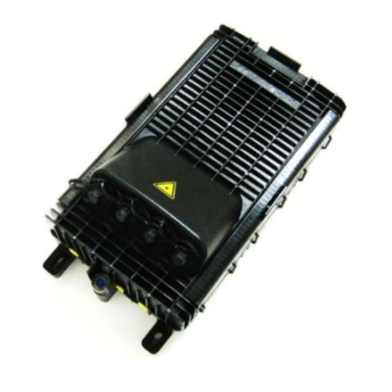
MINI-OTE 300 OPTICAL TERMINAL ENCLOSURE
Contents
1
General product information ............................................. 1
1.1
Cable types ........................................................................... 1
1.2
Tools and materials required .............................................. 2
. 1 .3..
Closure.specifications ......................................................... 2
2
Product images .................................................................... 3
3
Warning and cautions ......................................................... 4
4
Kit contents .......................................................................... 4
4.1
Supplementary kits ............................................................. 6
5
Cable preparation ................................................................ 7
. 5 .1..
Inline.configurations ........................................................... 7
. 5 .1.1.
Mid-sheath.-.loose.buffer.tube.(LBT) ................................ 7
5.1.2
Mid-sheath - ribbon central core....................................... 9
5.1.3..
Stub-loose.buffer.tube.(LBT) ............................................ 10
5.1.4
Stub-ribbon central core .................................................. 12
5.2..
Butt.entry.configurations ................................................. 14
5.2.1..
Mid-sheath.-.loose.buffer.tube.(LBT) .............................. 14
1
General product information
CommScope's Mini-OTE 300 closure is a gel sealed fiber optic terminating enclosure designed for the telecom outside
plant network. The closure is available in 2, 4, 6, 8 and 12 port versions with full-size or mini-size DLX® hardened adapters
with options for factory installed splitter or CWDM. The closure has a maximum splice capacity of 40 splices. It is suitable
for deployment in aerial, pole, pedestal, and below grade applications. The Mini-OTE 300 allows for both in line and butt
configurations with 5 ports accepting standard flat drop up to ½" diameter cable for multiple combinations of feeder and
drop cables. Sealing is achieved by spring loaded gel technology, resulting in extremely convenient re-entry and resealing.
1.1
Cable types
The Mini-OTE 300 is designed for standard flat drop, with or without toning wire, and loose buffer tube and central core tube
up to ½" diameter cable. Provisions are provided for shielded cable grounding. Fiber types include single fiber 250 micron,
flat matrix ribbon, and rollable ribbon fiber.
For cables that are ½" diameter it may be necessary to remove the plastic ring-strip that is located above the lower gel block,
such as 96F.
Rev. E
Plastic Ring Strip
5.2.2
Mid-sheath - ribbon central core..................................... 16
5.2.3..
Stub-loose.buffer.tube.(LBT) ............................................ 17
5.2.4
Stub-ribbon central core .................................................. 19
6
Cable bonding and grounding ......................................... 21
7
Cable retention ................................................................. 22
8
Fiber organizing/storage, routing and splicing ............. 23
8.1..
Mid-sheath.-.loose.buffer.tube.(LBT) .............................. 23
8.2..
Stub-loose.buffer.tube.(LBT) ............................................ 25
8.3
Mid-sheath ribbon central core ....................................... 27
8.4
Stub ribbon central core ................................................... 29
9
Closing/securing closure .................................................. 31
10
Mounting closure .............................................................. 32
11
Hardened drop cable installation .................................... 34
12
Trademarks and patents .................................................. 37
13
Contact information .......................................................... 37
Cut & Remove For Large Cables
© 2021 CommScope, Inc. All Rights Reserved
Installation Guide
Page 1 of 37
Advertisement
Table of Contents

Subscribe to Our Youtube Channel
Related Manuals for CommScope MINI-OTE 300


Summary of Contents for CommScope MINI-OTE 300
-
Page 1: Table Of Contents
Cable types The Mini-OTE 300 is designed for standard flat drop, with or without toning wire, and loose buffer tube and central core tube up to ½” diameter cable. Provisions are provided for shielded cable grounding. Fiber types include single fiber 250 micron, flat matrix ribbon, and rollable ribbon fiber. -
Page 2: Tools And Materials Required
• Flathead #2 screwdriver. Closure.specifications The Mini-OTE 300 is a unique solution for splicing, termination and pass-through cable requirements in fiber-to-the-x (FTTx) architectures. • Terminal is re-enterable, swinging open on a hinge for quick access and easy service and maintenance. -
Page 3: Product Images
Product images MINI-OTE 300 OPTICAL TERMINAL ENCLOSURE Page 3 of 37 © 2021 CommScope, Inc. All Rights Reserved... -
Page 4: Warning And Cautions
Install the product in a location where the fiber technician can easily access, connect and disconnect cables to the product. Kit contents For safe and stable use, the product should be installed using the following components found in the Mini-OTE 300 kit. Item Item... - Page 5 Item 4 Item 5 Item 6 Item 7 Item 8 Item 9 Item 10 Item 11 Item 12 Item 13 Item 14 Item 15 Item 16 Item 17 Item 18 Page 5 of 37 © 2021 CommScope, Inc. All Rights Reserved...
-
Page 6: Supplementary Kits
Bolts - 7/16” hex head (4) • Cable ties (2) Strand Mount Kit: # 760235507 OTE-M-STRAND BRKT • Brackets wth hardware (2) • Lock Washers (2) • Bolts (2) Page 6 of 37 © 2021 CommScope, Inc. All Rights Reserved... -
Page 7: Cable Preparation
Cut strength member(s) 1¾” from end of sheath openings. See Figure 1. 5.1.1.3 If flat drop has a trace wire, cleanly cut away 4” of wire from end sheath opening. See photos 1-2. Photo 1 Photo 2 Page 7 of 37 © 2021 CommScope, Inc. All Rights Reserved... - Page 8 Figure 2 5.1.1.12 Cut fibers to be spliced 41” from the buffer tube opening from incoming signal side of cable Proceed to section 8, Fiber organizing/storage, routing and splicing. Page 8 of 37 © 2021 CommScope, Inc. All Rights Reserved...
-
Page 9: Mid-Sheath - Ribbon Central Core
Note: Straighten steel strength members back into original position. Photo 12 Photo 13 Photo 14 If cable is shielded and to be grounded, proceed to Section 6. Proceed to Section 7 to assemble cable retention hardware. Page 9 of 37 © 2021 CommScope, Inc. All Rights Reserved... -
Page 10: Stub-Loose.buffer.tube.(Lbt)
Inline Stub (Cable End) Configuration 5.1.3.1 Remove 55” of outer sheath from end of cable. See Figure 4. Figure 4 5.1.3.2 Cut strength member(s) 1¾” from end of sheath openings. See Figure 4. Page 10 of 37 © 2021 CommScope, Inc. All Rights Reserved... - Page 11 If all fibers in a LBT are not to be spliced, route to storage area. Tray stack may be removed for easier access to storage. See photos 26-29. Photo 26 Photo 27 Photo 28 Photo 29 Page 11 of 37 © 2021 CommScope, Inc. All Rights Reserved...
-
Page 12: Stub-Ribbon Central Core
Remove core tube from ribbon leaving ½” core tube, measured from the cable sheath openings. See Figure 7. 5.1.4.4 Cut one ½” long piece of black felt tape and wrap around core tube. See photos 30-32. Page 12 of 37 © 2021 CommScope, Inc. All Rights Reserved... - Page 13 Remove ribbon containing fiber(s) to be spliced from fiber stack. 5.1.4.11 If ribbons are not to be spliced, route to storage area. Tray stack may be removed for easier access to storage. See photos 39-42. Page 13 of 37 © 2021 CommScope, Inc. All Rights Reserved...
-
Page 14: Butt.entry.configurations
Cut strength member(s) 1¾” from end of sheath openings. See Figure 8. 5.2.1.3 If Flat Drop has trace wire, cleanly cut away 4” of trace wire from end of sheath opening. See photos 43-44. Photo 43 Photo 44 Page 14 of 37 © 2021 CommScope, Inc. All Rights Reserved... - Page 15 Remove 46” of buffer tube between the two marks. See Figure 9. Figure 9 5.2.1.10 Cut fibers to be spliced 46” from the buffer tube opening, on the incoming signal side. Page 15 of 37 © 2021 CommScope, Inc. All Rights Reserved...
-
Page 16: Mid-Sheath - Ribbon Central Core
Secure each spiral wrap to core tube with cable tie. 5.2.2.8 Repeat on other side of sheath opening. See photos 54-55. Note: Straighten steel strength members back into original position. Photo 54 Photo 55 Page 16 of 37 © 2021 CommScope, Inc. All Rights Reserved... -
Page 17: Stub-Loose.buffer.tube.(Lbt)
Proceed to section 8, Fiber organizing/storage, routing and splicing. 5.2.3 Stub.-.loose.buffer.tube.(LBT) Butt Stub (Cable End) Configuration 5.2.3.1 Remove 55” of outer sheath from end of cable. See Figure 11. Figure 11 Page 17 of 37 © 2021 CommScope, Inc. All Rights Reserved... - Page 18 If all fibers in a LBT are not to be spliced, route LBT to storage area. Tray stack may be removed for easier access to storage. See photos 66-68. Photo 66 Photo 67 Photo 68 Page 18 of 37 © 2021 CommScope, Inc. All Rights Reserved...
-
Page 19: Stub-Ribbon Central Core
Cut 1 piece of spiral wrap 10” in length. 5.2.4.6 Wrap spiral wrap around ribbon so that it wraps around the ½” core tube. 5.2.4.7 Secure with cable tie. See photos 72-74. Page 19 of 37 © 2021 CommScope, Inc. All Rights Reserved... - Page 20 Tray stack may be removed for easier access to storage. See photos 78-81. Photo 78 Photo 79 Photo 80 Photo 81 Proceed to Section 8 Fiber organizing/storage, routing and splicing. Page 20 of 37 © 2021 CommScope, Inc. All Rights Reserved...
-
Page 21: Cable Bonding And Grounding
Caution: Do not use braided or stranded ground wire when installing a ground through a port on the Mini-OTE 300 closure. A solid ground wire is required to prevent a leak path and make a proper seal. Photo 84 Page 21 of 37 © 2021 CommScope, Inc. All Rights Reserved... -
Page 22: Cable Retention
See photos 86-87. Photo 86 Photo 87 Insert strength member(s) into lug and tighten. See photo 88. Photo 88 Page 22 of 37 © 2021 CommScope, Inc. All Rights Reserved... -
Page 23: Fiber Organizing/Storage, Routing And Splicing
Route LBT to be spliced to routing tray. See photo 94. Note: Left side LBTs to be routed first. Right side LBTs to cross over LBTs from left side. Otherwise, route buffer tube directly to routing tray. Photo 94 Page 23 of 37 © 2021 CommScope, Inc. All Rights Reserved... - Page 24 Route express fibers and fibers cut “dead to field” to the Feed Thru tray. See photo 101 Photo 101 8.1.7 Route fiber(s) to be spliced to top tray. See photos 102-104. Page 24 of 37 © 2021 CommScope, Inc. All Rights Reserved...
-
Page 25: Stub-Loose.buffer.tube.(Lbt)
Stub.loose.buffer.tube.(LBT) Use this section for Inline and Butt stub LBT 8.2.1 Store one loop of buffer tube and proceed to routing tray. See photos 105-106. Photo 105 Photo 106 Page 25 of 37 © 2021 CommScope, Inc. All Rights Reserved... - Page 26 Micro Grommet LBT Photo 107 Photo 108 Photo 109 Photo 110 Photo 111 Photo 112 8.2.5 Route fiber(s) not to be spliced to Feed thru tray. See photo 113. Photo 113 Page 26 of 37 © 2021 CommScope, Inc. All Rights Reserved...
-
Page 27: Mid-Sheath Ribbon Central Core
Replace dust cover on tray after splicing. Mid-sheath ribbon central core 8.3.1 Route ribbon to tray entry points and mark ribbon 1” beyond grommet locations. 8.3.2 De-ribbonize fiber between marks. See photos 117-118. Page 27 of 37 © 2021 CommScope, Inc. All Rights Reserved... - Page 28 Cut fibers to be spliced 41” from the signal input side. 8.3.7 Route express fibers onto feed thru tray. See photo 123. Photo 123 8.3.8 Route fibers to be spliced to top tray. See photos 124-126. Page 28 of 37 © 2021 CommScope, Inc. All Rights Reserved...
-
Page 29: Stub Ribbon Central Core
Store one loop of fibers to be spliced and route ribbon to tray entry point. 8.4.2 At tray entry point, mark ribbon 1” beyond grommet location. See photos 127-128. Photo 127 Photo 128 8.4.3 De-ribbonize fiber from mark to end of fiber. Page 29 of 37 © 2021 CommScope, Inc. All Rights Reserved... - Page 30 Route fibers that will not be spliced onto Feed Thru tray. See photo 133. Photo 133 8.4.7 Route fibers to be spliced to top splice tray. See photos 134-136. Photo 134 Photo 135 Page 30 of 37 © 2021 CommScope, Inc. All Rights Reserved...
-
Page 31: Closing/Securing Closure
Install port plugs into all unused ports, including ground port if no ground wire. See photo 137. Photo 137 9.4.3 Close lid. 9.4.4 Ensure all port plugs, ground wire (if present) and cables are properly aligned. Page 31 of 37 © 2021 CommScope, Inc. All Rights Reserved... -
Page 32: Mounting Closure
Photo 143 Photo 144 Photo 145 Photo 146 10.4.3 For strand mounting, assemble strand clamps or supplementary mounting brackets to back of housing. 10.4.4 Assemble to line. See photos 147-148. Page 32 of 37 © 2021 CommScope, Inc. All Rights Reserved... - Page 33 Photo 147 Photo 148 10.4.5 For pole mounting, assemble supplementary mounting brackets to back of housing and assemble to pole. See photo 149. Photo 149 Page 33 of 37 © 2021 CommScope, Inc. All Rights Reserved...
-
Page 34: Hardened Drop Cable Installation
Use the 216C key tool (accessory) to unscrew the dust cap (see Figure 15) from the Mini-OTE optical port 11.4 Clean both the optical port adapter and the drop cable connector (requires accessory kit FHD-ACC-CLNKIT1) as specified in ADCP-96-067. Page 34 of 37 © 2021 CommScope, Inc. All Rights Reserved... - Page 35 Inspect the drop cable connector O-rings for dryness and wipe clean of any residual lube and dust/dirt/debris. 11.15 Thread the drop cable dust cap onto the drop cable connector coupling nut and tighten until finger tight (see Figure 17). Page 35 of 37 © 2021 CommScope, Inc. All Rights Reserved...
- Page 36 Figure 19. Note: The drop cable connector uses angled SC type connectors. Make sure the high side of the connector end-face is pointing in the direction of the cleaning motion. Page 36 of 37 © 2021 CommScope, Inc. All Rights Reserved...
-
Page 37: Trademarks And Patents
Trademarks and patents All trademarks identified by ® or ™ are registered trademarks or trademarks, respectively, of CommScope, Inc. This document is for planning purposes only and is not intended to modify or supplement any specifications or warranties relating to CommScope products or services.
Need help?
Do you have a question about the MINI-OTE 300 and is the answer not in the manual?
Questions and answers