Table of Contents
Advertisement
Quick Links
Advertisement
Table of Contents

Related Manuals for CommScope ION-M7P


Summary of Contents for CommScope ION-M7P
- Page 1 Optical Remote Unit ION™-M7P/7P/85P/19P (ML-Cabinet) Manual MF0145A4A...
- Page 2 ION™-M7P/7P/85P/19P (ML-cab) © Copyright 2011 CommScope, Inc. All rights reserved. Andrew Solutions is a trademark of CommScope, Inc. All information contained in this manual has been revised thoroughly. Yet Andrew Solutions accepts no liability for any omissions or faults. Andrew Solutions reserves the right to change all hard- and software characteristics without notice.
-
Page 3: Table Of Contents
TABLE OF CONTENTS 1. GENERAL 1.1. USED ABBREVIATIONS 1.2. HEALTH AND SAFETY WARNINGS 1.3. ABOUT ANDREW SOLUTIONS 1.4. INTERNATIONAL CONTACT ADDRESSES FOR CUSTOMER SUPPORT 2. FUNCTIONAL DESCRIPTION 2.1. PURPOSE 2.2. THE ION™-M7P/7P/85P/19P (INTELLIGENT OPTICAL NETWORK; MMR) 3. COMMISSIONING 3.1. MECHANICAL INSTALLATION 3.1.1. - Page 4 5. MAINTENANCE 5.1. GENERAL 5.2. REPLACING THE FAN UNIT 5.3. CLEANING THE HEAT SINK 6. APPENDIX 6.1. ILLUSTRATIONS 6.2. SPECIFICATIONS 6.2.1. Electrical Specifications 6.2.2. Mechanical Specifications 6.2.3. Environmental and Safety Specifications 6.3. SPARE PARTS 7. INDEX Manual ION-M7P-7P-85P-19P Page 4 MF0145A4A.doc...
- Page 5 3-3 Pole-mounting kit, view from different sides ..........17 figure 3-4 Pole-mounting, ML-cabinet, assembly drawing ........18 figure 3-5 Pole mounting of RU, finished ..............18 figure 3-6 Connector flange of ION-M7P/7P/85P/19P ..........20 figure 3-7 RS485 connector..................20 figure 3-8 Grounding bolt ..................21 figure 3-9 Grounding bolt, schematic view..............
-
Page 6: General
PCMCIA Personal Computer Modem Communication International Association Personal Communication System PSTN Public Switched Telephone Network R&TTE Radio & Telecommunications Terminal Equipment Revision Radio Frequency Radio Link Protocol RSSI Receive Signal Strength Indication Real-Time Clock Receiver Manual ION-M7P-7P-85P-19P Page 6 MF0145A4A.doc... -
Page 7: Health And Safety Warnings
Operation of this equipment in a residential area is likely to cause harmful interference in which case the user will be required to correct the interference at his own expense. Manual ION-M7P-7P-85P-19P Page 7 MF0145A4A.doc... - Page 8 17. Laser radiation! Do not stare into the beam; do not view it directly or with optical instruments. Manual ION-M7P-7P-85P-19P Page 8 MF0145A4A.doc...
-
Page 9: About Andrew Solutions
Andrew Wireless Systems GmbH has unparalleled experience in providing RF coverage and capacity solution for wireless networks in both indoor and outdoor environment and belongs to Andrew Solutions, a CommScope Company. Andrew Solutions is the foremost supplier of one-stop, end-to-end radio frequency (RF) solutions. -
Page 10: International Contact Addresses For Customer Support
1.4. INTERNATIONAL CONTACT ADDRESSES FOR CUSTOMER SUPPORT Americas: Canada United States Andrew Solutions, Andrew Solutions Canada Andrew LLC, A CommScope Company 620 North Greenfield Parkway 620 North Greenfield Parkway Mail Garner, NC 27529 Mail Garner, NC 27529 U.S.A. U.S.A. +1-905-878-3457 (Office) - Page 11 +41-62-386-1261 E-mail WIsupport.austria@commscope.com E-mail WIsupport.ch@commscope.com Italy Spain and Portugal Andrew Solutions España S.A. Commscope Italy S.r.l., Faenza, Italy A Commscope Company Avda. de Europa, 4 - 2ª pta. Via Mengolina, 20 Parque Empresarial La Moraleja Mail 48018 Faenza (RA) Mail...
-
Page 12: Functional Description
The ION-M7P/7P/85P/19P transports signals on the RF layer in a very inexpensive manner. This means that multiple operators and multiple technologies are moved simultaneously from a cluster of base stations to a remote location over the same fiber. - Page 13 The ION-M7P/7P/85P/19P is available in single (SISO) or multi-channel (MIMO) configuration supporting 700 MHz, LTE, 850 MHz, and 1900 MHz in parallel. It has been specifically tested and optimized for LTE, OFDM, CDMA, and WCDMA signals. The ION is easily set-up and supervised via a graphical user interface (GUI). Remote Units can be commissioned through the use of built-in test equipment.
-
Page 14: Commissioning
Remote Unit. For details refer to section 7.2.2 Mechanical Specification. Install the unit vertically with the fan unit at the top. A maximum tilt angle of 25° from a vertical position must be kept, as in the following illustrations: Manual ION-M7P-7P-85P-19P Page 14 MF0145A4A.doc... - Page 15 The mounting procedures for a stand-alone Remote Unit without optional accessories are described and illustrated in the following sections. For further information regarding special mounting procedures including mounting of accessory equipment, please see separate manual. Manual ION-M7P-7P-85P-19P Page 15 MF0145A4A.doc...
-
Page 16: Wall Mounting Of Ru
3-2 RU wall mounting * The dowels are not part of the delivery since the suitable type depends on the on-site conditions (material of wall). Therefore, use dowels that are appropriate for the mounting surface. Manual ION-M7P-7P-85P-19P Page 16 MF0145A4A.doc... -
Page 17: Pole Mounting Of Ru
Hang the Remote Unit into the hooks of the upper mounting bracket and screw the Remote Unit to the lower mounting bracket. Manual ION-M7P-7P-85P-19P Page 17 MF0145A4A.doc... -
Page 18: Figure 3-4 Pole-Mounting, Ml-Cabinet, Assembly Drawing
Note: All unmarked screw joints have nominal tightening torque values according to QA 7.5.1.090/F1011P0. figure 3-4 Pole-mounting, ML-cabinet, assembly drawing Pole mounting finished (RU mounted to pole) L_G3219X000 figure 3-5 Pole mounting of RU, finished Manual ION-M7P-7P-85P-19P Page 18 MF0145A4A.doc... -
Page 19: Electrical Installation
(external surge protection), depending on the individual application, in order to avoid damage caused by overcurrent. 13. Observe the labels on the front panels before connecting or disconnecting any cables. Manual ION-M7P-7P-85P-19P Page 19 MF0145A4A.doc... -
Page 20: Connections
Grounding bolt Antenna connector 700/ 850 MHz figure 3-6 Connector flange of ION-M7P/7P/85P/19P Control Connector (RS485 / RS232) This 8-pin male connector (type: Binder Series 712) primarily supports control of the Extension Unit via RS485 bus. Assignment not connected... -
Page 21: Grounding
Andrew e-catalog. Do NOT use your hands or any other tool (e.g. a pair of pliers)! This might cause damage to the connector and lead to a malfunction of the Remote Unit. Manual ION-M7P-7P-85P-19P Page 21 MF0145A4A.doc... -
Page 22: Power Connection
120 Volt / 20 Amp max. or 240 Volt / 16 Amp, single-phase, 50 / 60 Hz AC service is needed, i.e. the external AC breaker should be 20 Amps max. for 120-Volt service or 16 Amps for 240-Volt service. For the DC power supply, observe the local regulations of the DC service provider. Manual ION-M7P-7P-85P-19P Page 22 MF0145A4A.doc... -
Page 23: Optical-Fiber-Cable Connection - Rules
Using high-grade alcohol and lint-free cotton cleaning swabs, clean the end of the fiber-optic cable that will be inserted in the optical connectors on the donor interface box. Use a fiber end-face inspection tool to scan both, the class fiber and its surrounding area. Manual ION-M7P-7P-85P-19P Page 23 MF0145A4A.doc... - Page 24 8. Repeat steps 5 through 7 until endface is clean. Note: For a more detailed description please refer to: http://www.cisco.com/en/US/tech/tk482/tk876/technologies_white_paper09186 a0080254eba.shtml Manual ION-M7P-7P-85P-19P Page 24 MF0145A4A.doc...
-
Page 25: Protective Plug
A protective plug is provided for the connection of the fiber-optic cables. figure 3-11 Protective-plug assembly Note: Only high-quality connectors must be used for this type of plug. Qualified brands are Diamond or Huber & Suhner. Manual ION-M7P-7P-85P-19P Page 25 MF0145A4A.doc... - Page 26 Use a spanner one groove for one contact or two with opening screw grooves for two contacts) over the backshell tight (no gap). cable(s) and push them into the backshell. No gap Seals with one groove Manual ION-M7P-7P-85P-19P Page 26 MF0145A4A.doc...
-
Page 27: Protective-Tube Kit
As additional protection for the optical fibers, this connector type can be supplemented by a special tube kit. To fasten the tube correctly, first unscrew the clamp ring (if already installed) of the original plug kit. Then, proceed according to the following instruction: Manual ION-M7P-7P-85P-19P Page 27 MF0145A4A.doc... -
Page 28: Figure 3-12 Tube-Kit Installation
Protective tube the backshell! Push the fiber-optic cable carefully through the tube until it comes out at the other end. G1055M0 figure 3-12 Tube-kit installation Manual ION-M7P-7P-85P-19P Page 28 MF0145A4A.doc... -
Page 29: Commissioning
Do not damage the warranty labels on the devices. The warranty is void if the seals are broken. Ensure that all connections have been performed according to section 3.2.1 General. Manual ION-M7P-7P-85P-19P Page 29 MF0145A4A.doc... - Page 30 PIN 3 Electrical connections Mains cable Connect AC power to the power cable. = n.c. Connecting kit Ensure there is a circuit breaker between mains and RU. PIN 4 = Mains Switch mains power on. Manual ION-M7P-7P-85P-19P Page 30 MF0145A4A.doc...
- Page 31 ALC alarm: Decrease DL input power of service affected band. VSWR alarm: Check antenna and cable. Finished setting up all RUs? Proceed to MU to set up the SW Output: Go to MU All RUs okay. Manual ION-M7P-7P-85P-19P Page 31 MF0145A4A.doc...
- Page 32 For your notes: Manual ION-M7P-7P-85P-19P Page 32 MF0145A4A.doc...
-
Page 33: Alarms
A new alarm message will be generated if the alarm is interrupted for at least five seconds after alarm clearance by the RU. 4.3. ALARM STATUS Refer to the corresponding software documentation of the Master Unit for details. Manual ION-M7P-7P-85P-19P Page 33 MF0145A4A.doc... -
Page 34: Status Led Alarms
Check power supply cabling. Check power supply. table 4-1 Status LED alarms For the position of the status LED see section 3.2.2 Connections. Explicit troubleshooting is available in the MU software, (software manual or WEB Interface). Manual ION-M7P-7P-85P-19P Page 34 MF0145A4A.doc... -
Page 35: External Alarm Inputs And Outputs
As accessory equipment the alarm kit is available to connect external devices to the external alarm inputs and outputs (for ID No see section 6.3 Spare Parts). Manual ION-M7P-7P-85P-19P Page 35 MF0145A4A.doc... -
Page 36: Figure 4-3 Alarm Inputs And Outputs, Standard
The status of the Remote Unit can be checked via the Master Unit (for details please refer to the software manual of the Master Controller). Locally, the status can be checked at the LED, see section 4.4 Status LED Alarms. Manual ION-M7P-7P-85P-19P Page 36 MF0145A4A.doc... - Page 37 These cleaning intervals depend mainly on the location of the Remote Unit and the corresponding degree of pollution. Maintenance of the ION-M7P/7P/85P/19P should be performed by replacing only components that are contained in this section. Take care not to unintentionally damage the seals on the modules to maintain warranty.
-
Page 38: Figure 5-1 Fan Unit And Heat Sink
8. Then, mains power can be reconnected and the unit can be powered up. In order not to exceed the specified torque of 82 Ncm, use an appropriate tool! In order not to exceed the specified torque of 330 Ncm, use an appropriate tool! Manual ION-M7P-7P-85P-19P Page 38 MF0145A4A.doc... - Page 39 Take care that the material is not scratched or damaged. 6. After cleaning the heat sink, mount the fan unit and the fan guard again according to section 5.2 Replacing the Fan Unit. Then, reconnect mains power and power up the unit. Manual ION-M7P-7P-85P-19P Page 39 MF0145A4A.doc...
-
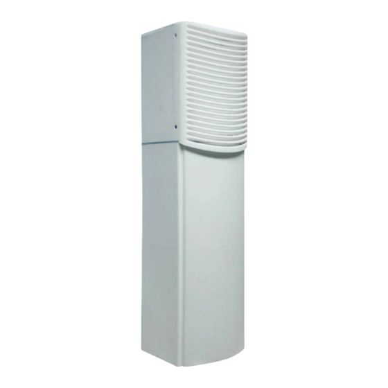
Page 40: Figure 6-1 Cabinet Drawing
6. APPENDIX 6.1. ILLUSTRATIONS G3219M0 figure 6-1 Cabinet drawing Manual ION-M7P-7P-85P-19P Page 40 MF0145A4A.doc... - Page 41 Safety Specifications leaflet of the supplier, related to ETS 300 019 (European Telecommunication Standard). Operating temperature range -33 to +50°C RF part IP67 Ingress protection Fan part IP55 All figures are typical values, unless otherwise stated. All data is subject to change without notice. Manual ION-M7P-7P-85P-19P Page 41 MF0145A4A.doc...
- Page 42 To replace an FRU, use the appropriate tools. Replacement tools may be ordered from the supplier. If any FRU not contained in the following list needs to be replaced, please contact customer service for additional instructions. Spare Parts List of the Remote Unit ION-M7P/7P/85P/19P Designation: ID No:...
- Page 43 Spare Parts ............42 Fiber-Optical Components Specifications Cleaning Procedure ......... 24 Electrical ............41 System Installation........... 23 Environmental and Safety........ 41 Flange Connector Mechanical ............41 5 poles ............. 35 7 poles ............. 35 Troubleshooting............ 36 Grounding............. 21 Manual ION-M7P-7P-85P-19P Page 43 MF0145A4A.doc...
Need help?
Do you have a question about the ION-M7P and is the answer not in the manual?
Questions and answers