CommScope NG4access Manual
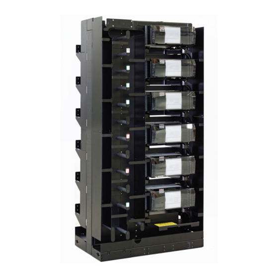
Odf platform for integrated frame, rear side routing
Hide thumbs
Also See for NG4access:
- Installation manual (58 pages) ,
- Installation instructions manual (30 pages) ,
- User manual (30 pages)
Table of Contents
Advertisement
Quick Links
NG4access ODF Platform
Rear Side Routing Guide
for Integrated Frame
TC-96285-IP • Rev A • February 2020
Table of Contents
FIBERGUIDE SYSTEM
IFC FromOverhead .................. 2
IFC From Under Floor .............. 3
Breakout ............................... 4
Breakout ............................... 5
Breakout ............................... 6
(Preferred Routing).................. 7
(Overhead)............................. 8
(Under Floor).......................... 9
Chassis..................................10
Installing Adapter Packs ..........11
Tray .....................................13
Customer Information ............ 14
27034-A
CommScope Technical Assistance
http://www.commscope.com/SupportCenter
860652745 Rev A
Advertisement
Table of Contents

Related Manuals for CommScope NG4access


Summary of Contents for CommScope NG4access
-
Page 1: Table Of Contents
NG4access ODF Platform Rear Side Routing Guide for Integrated Frame TC-96285-IP • Rev A • February 2020 Table of Contents FIBERGUIDE SYSTEM IFC FromOverhead ....2 IFC From Under Floor ....3 NG4 C-MODs With 120-Inch Breakout ....... 4 864 NG4 C-MODs With 76-Inch Breakout ....... -
Page 2: Ifc Fromoverhead
(D) to chassis. If on left side, route through cross- frame trough (E) and around radius limiter (F) to chassis. Snap C-MOD into tray (see pages 12-13). 27039-A © 2020 CommScope, Inc. Page 2... -
Page 3: Ifc From Under Floor
(D). (*Spool kit must be ordered separately.) If on left side, route through crossframe trough (E), around radius limiter (F); snap C-MOD into tray (see pages 12-13). Take up slack on highest spool within reach (G). 27040-A www.commscope.com Page 3... -
Page 4: Ng4 C-Mods With 120-Inch Breakout
Floor option, the fanouts would be located near the lowest chassis location. FIBERGUIDE SYSTEM 577-864 289-576 CABLE 4 1-288 577-864 CABLE 3 289-576 1-288 577-864 289-576 CABLE 2 1-288 577-864 CABLE 1 289-576 1-288 97042-A © 2020. CommScope, Inc. Page 4... -
Page 5: 864 Ng4 C-Mods With 76-Inch Breakout
CABLE FINGER CABLE 3 1-288 577-864 FANOUT LOCATION CABLE FINGER CABLE 3 289-576 1-288 CABLE 2 577-864 289-576 FANOUT LOCATION CABLE 2 CABLE FINGER CABLE 1 1-288 577-864 FANOUT LOCATION CABLE FINGER CABLE 1 289-576 1-288 97043-A www.commscope.com Page 5... -
Page 6: Ifc Fanout Cables With 60-Inch Breakout
CABLE FINGER CABLE 5 FANOUT LOCATION CABLE FINGER CABLE 3 CABLE 4 FANOUT LOCATION CABLE FINGER CABLE 3 FANOUT LOCATION CABLE 2 CABLE FINGER CABLE 2 FANOUT LOCATION CABLE FINGER CABLE 1 CABLE 1 FANOUT LOCATION 97090-A www.commscope.com Page 6... -
Page 7: Fot Patch Cord From Overhead (Preferred Routing)
If on left side, route cable through crossframe trough (D), around radius limiter and into chassis (E). Plug connector into adapter port (see pages 11, 13). Hang slack over FOTSP spool (F). 27041-A © 2020. CommScope, Inc. Page 7... -
Page 8: Osp/Ifc To Splice Chassis (Overhead)
From Overhead Clamp cable at top right of frame (A) using standard clamp. Route through outer channel (B) to area below splice chassis (C). For splice chassis detail, refer to TECP-90-704. SPLICE CHASSIS 27036-A © 2020. CommScope, Inc. Page 8... -
Page 9: Osp/Ifc To Splice Chassis (Under Floor)
Clamp cable at bottom right using under- floor clamp (A). Route through outer chan- nel (B) around spool (C). Route cable to area below splice chassis (D). For splice chassis details, refer to TECP-90-704. SPLICE CHASSIS 97037-A www.commscope.com Page 9... -
Page 10: Pigtail C-Mod To Splice
PIGTAIL cable down and CABLED around radius MODULE limiter (F), through crossframe trough (G), and then through inner chan- nel (C) to area below splice chassis (D). instructions on installing C-MOD, see pages SPLICE CHASSIS 12-13. 25848-A www.commscope.com Page 10... -
Page 11: Installing Adapter Packs
Flip these pages clockwise to view them horizontally. -
Page 12: Installing A C-Mod, Vam, Or Mpo-Module Into Access Tray
Flip this page clockwise to view it horizontally. -
Page 13: Routing Cables From Access Tray
Flip this page clockwise to view it horizontally. -
Page 14: Customer Information
Flip this page clockwise to view it horizontally.
Need help?
Do you have a question about the NG4access and is the answer not in the manual?
Questions and answers