Advertisement
Quick Links
NC 42U/45U/47U-Type Network Cabinet Assembly Instructions
General
®
CommScope
Network Cabinets (NC) are designed to support and enhance the installation of the network
infrastructure. The cabinets are available in 600mm and 800mm widths and 600mm and 800mm depths. The
cabinets are available in a wide variety of front and rear door materials and configurations.
Assembly of the 800mm x 800mm NC 42U-Type Network Cabinet is illustrated in this document, although the
instructions cover other depths, widths and heights as well as standard door installation. Instructions for
assembly/installation of optional equipment are provided with that equipment.
It is highly recommended that installation of this product be performed by a qualified and experienced
installer. Improper installation of this product could result in damage to the product, other equipment,
or personal injury.
personal injury resulting from improper fastening or misuse of information presented in this
document. Cabinets must be wired per applicable sections of the National Electrical Code
(NEC). If grounding is required, appropriate grounding hardware approved by the NEC must
be used
www.commscope.com
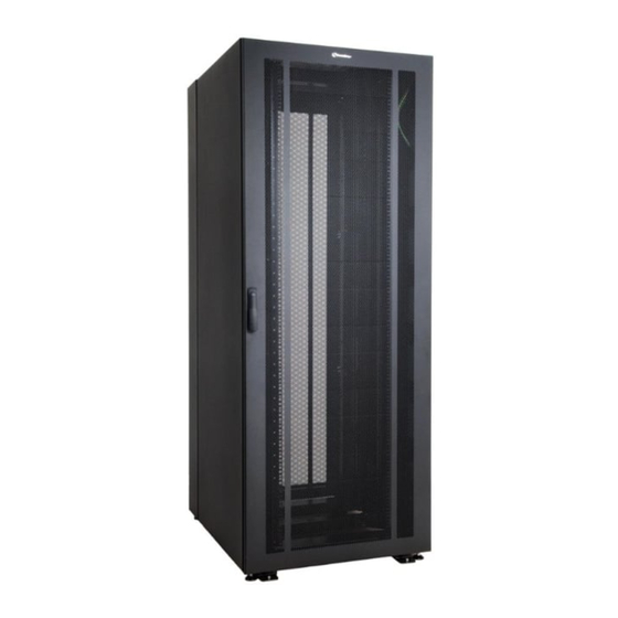
800mm x 800mm NC 42U-Type Network Cabinet
WARNING
CommScope cannot be held responsible for damage to equipment or
© 2012 CommScope, Inc. All rights reserved
Instruction Sheet 860445097
Issue 4, January 2013
For RoHS Inquiries:
CommScope Inc.
Page 1 of 24
Corke Abbey, Bray
Co. Dublin, Ireland
Attn: Legal Department
Advertisement

Related Manuals for CommScope NC 42U-Type


Summary of Contents for CommScope NC 42U-Type
- Page 1 Assembly of the 800mm x 800mm NC 42U-Type Network Cabinet is illustrated in this document, although the instructions cover other depths, widths and heights as well as standard door installation. Instructions for assembly/installation of optional equipment are provided with that equipment.
-
Page 2: How To Contact Us
1-800-344-0223. Outside the United States, contact your local account representative or Authorized Business Partner. Within the United States, report any missing/damaged parts or any other issues to CommScope Customer Claims at 1-866-539-2795. Outside the United States, contact your local account representative or Authorized Business Partner. Tools Required... -
Page 3: Warning! Important Safety Instructions
Never extend more than one sliding unit at a time. • Many equipment configurations are possible in the CommScope cabinet. The amount of force required to tip or destabilize a cabinet will differ with each configuration. Read and follow all equipment manufacturer’s specifications and instructions for assembly, installation, and safety. - Page 4 860445097 www.commscope.com Instruction Sheet Assembly Instructions IMPORTANT: A clean, flat, level, protected floor area should be provided for cabinet assembly to prevent damage to parts. Note: The assembly process may require two persons at certain stages to lift, position and hold cabinet components in place.
- Page 5 860445097 Issue 4, January 2013 Side Brace Member Pack I Quantity Description Side brace members 6 pair Locking inserts Clamp Plate Pack (No Earthing) T Quantity Description Clamp plates Clamp Plate Pack (Earthing) T Quantity Description Primary earth point label...
- Page 6 860445097 www.commscope.com Instruction Sheet Assembly Hardware and Fasteners Identify fasteners and assembly hardware from the illustrations below. Page 6 of 24...
- Page 7 860445097 Issue 4, January 2013 600mm x 800mm Network Cabinet Page 7 of 24...
- Page 8 860445097 www.commscope.com Instruction Sheet 800mm x 800mm Network Cabinet Page 8 of 24...
- Page 9 860445097 Issue 4, January 2013 Cabinet Main Component Part Identification Part Quantity Description Designation Bottom X-frame Frame A Right-front vertical member with mounting rail Vertical B Left-front vertical member with mounting rail Vertical C Vertical D Right-rear vertical member with mounting rail...
- Page 10 860445097 www.commscope.com Instruction Sheet Step 3 – Assemble Vertical Members to Bottom X-Frame Parts required for this step: • Frame A • Verticals B, C, D and E with mounting rails • (8) M8 x 65 counter-sunk bolts • (3) Clamp plates •...
- Page 11 860445097 Issue 4, January 2013 Note: If cabinet requires a common earth connection, screw the M6 x 25 brass hex head screw with M6 earthing washer into center hole in clamp plate before assembling left front vertical to frame A. Apply primary earth point label to bottom of clamp plate below M6 hex screw.
- Page 12 860445097 www.commscope.com Instruction Sheet Step 4 – Assemble Top X-Frame to Vertical Members Parts required for this step: • Frame G • (4) Clamp plates with earthing harness • (8) M8 x 65mm counter-sunk bolts Vertical Orient front of frame G with...
- Page 13 860445097 Issue 4, January 2013 M8 x 65mm bolts Mounting rail Verticals Clamp plate positioned under Flip assembly and frame G mount verticals on Frame G Earthing opposite side harness 1. Orient front of frame G with front of frame A and position between the four verticals as shown.
- Page 14 860445097 www.commscope.com Instruction Sheet 2. Screw each foot to within 51mm (2-inches) from bottom of frame and tighten the locking hex nuts against frame to a snug fit. Do not fully tighten the feet locking nuts until the cabinet has been correctly positioned in its final point of installation.
- Page 15 860445097 Issue 4, January 2013 Step 7 – Disassemble Mounting Rails from Vertical Members (Right Side) No parts required for this step: Tap mounting rail forward to disengage tabs from slots Slot in vertical Tab on mounting rail Note: The mounting rails come pre-assembled to the vertical members and must be removed prior to installing the side braces.
- Page 16 860445097 www.commscope.com Instruction Sheet Step 8 – Install Side Brace Members (Right Side) Parts required for this step: • (3) Brace I members • (6) Brace member locking inserts Note: Tabs on brace I members will slide into slots in verticals and are installed in upper, middle and lower positions on both sides of the cabinet.
- Page 17 860445097 Issue 4, January 2013 Upper Side Brace Member (Right Side) Outside of Curved vertical section faces up Tap with a nylon hammer and out to lock in place Square holes in brace Uppermost set of square holes stamped in verticals...
- Page 18 860445097 www.commscope.com Instruction Sheet Lower Side Brace Members (Right Side) Lowermost set of square holes stamped in verticals Square holes in brace 1. Select a brace I and orient it between front and rear verticals so that curved side faces up and outward.
- Page 19 860445097 Issue 4, January 2013 Middle Side Brace Members (Right Side) 1. Select a brace I and orient it between front and rear verticals so that curved side faces up and outward. 2. Position middle brace I so that the row of square holes stamped into brace I align with the sixth set of square holes from the top of the verticals.
- Page 20 860445097 www.commscope.com Instruction Sheet Step 9 – Reinstall Side Mounting Rails (Right Side) Parts required for this step: • (2) Mounting rails (removed in Step 7) • (4) M6 x 12mm screws (removed in Step 7) 1. Beginning with either the front or rear, select the same mounting rail that was disassembled from that vertical and position it against the vertical.
- Page 21 860445097 Issue 4, January 2013 Step 10 – Disassemble Mounting Rails, Install Side Braces and Reassemble Mounting Rails (Left side) Parts required for this step: • (3) Brace I members • (6) Brace member locking inserts 1. Repeat Steps 7, 8, and 9 to disassemble mounting rails, install side braces, and reassemble mounting rails on the left side of the cabinet.
- Page 22 860445097 www.commscope.com Instruction Sheet Side Connect one leg of Vertical panel front earthing harness to upper corner of side panel Slide retaining latch on lower section of side panel into locked position 2. Connect one leg of the two front earthing wire harnesses at the following locations: •...
- Page 23 860445097 Issue 4, January 2013 Step 12 – Install Cabinet Doors and Complete Earthing Wire Connections Parts required for this step: • (1) Door P (front) • (1) Door O (rear) • (4) Hinge pins Insert hinge pins into right side...
- Page 24 860445097 www.commscope.com Instruction Sheet Pull latch out and rotate 90 counter-clockwise to close door 4. Pull door handle out and rotate counter-clockwise 90° to release the latch and then close the door. Turn door handle clockwise 90° to engage door latch and then push door handle back into door.
Need help?
Do you have a question about the NC 42U-Type and is the answer not in the manual?
Questions and answers