Table of Contents
Advertisement
Quick Links
TC-1554-IP
Rev. F, March 2024
http://www.commscope.com
1
About this manual
This manual describes the installation steps of the FOSC 650. The document starts with providing an overview of the
tools required to perform the installation. Also warnings and cautions are indicated, which should be observed before
starting the product installation.
Images in this manual are for reference only and are subject to change.
2
General product information
2.1
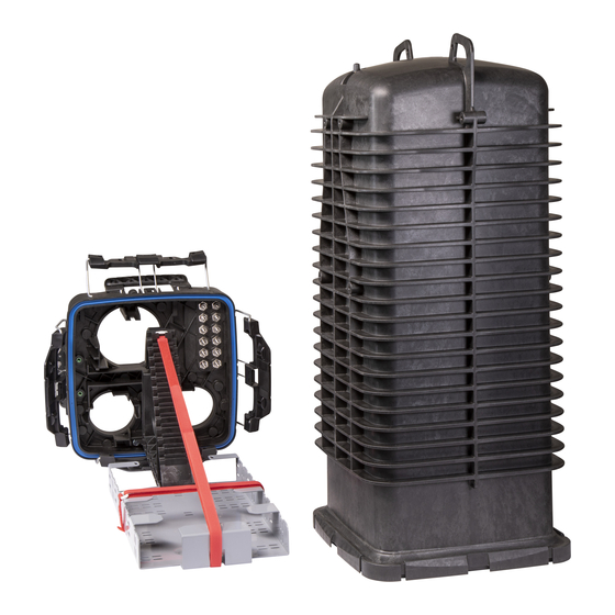
Dimensions
Small Gel Block Ports
NOVUX™ Fiber Optic System
FOSC 650
870 mm
34.25 Inches
1020 mm
40.16 Inches
Handle (x4)
Latch (x4)
page 1 / 23
© 2024 CommScope, Inc. All Rights Reserved
Installation Instructions
13.6 Inches
Ground Feed
Through Lugs
Gel Block Collar
Mounting Holes
Large Gel Block Port
External Bracket
Mounting Holes (x4)
345 mm
Advertisement
Table of Contents

Related Manuals for CommScope NOVUX FOSC 650


Summary of Contents for CommScope NOVUX FOSC 650
-
Page 1: About This Manual
1020 mm 40.16 Inches Handle (x4) Ground Feed Latch (x4) Through Lugs Gel Block Collar Mounting Holes Small Gel Block Ports Large Gel Block Port External Bracket Mounting Holes (x4) page 1 / 23 © 2024 CommScope, Inc. All Rights Reserved... -
Page 2: Cable Diameter Range
Regarding the small 4-way cable gel block: if both lower cable ports have cable diameters greater than 26 mm / 1 inch, then the maximum cable diameter in the upper cable ports will be 20 mm / 0.79 inches. page 2 / 23 © 2024 CommScope, Inc. All Rights Reserved... -
Page 3: Table Of Contents
8.2 Strength member fixation................7 Mount the closure................. 20 Cable installation................8 17.1 Wall mounting..................... 20 Routing..................... 9 17.2 Aerial mounting..................21 10.1 Preparation...................... 9 Disclaimer..................23 10.2 Route in basket....................10 Contact information..............23 Trays....................12 page 3 / 23 © 2024 CommScope, Inc. All Rights Reserved... -
Page 4: Abbreviations
Open the latch by pulling downwards. Then turn the latch down. Open the 4 latches and lift the dome away from the base and set aside until the end of the installation. page 4 / 23 © 2024 CommScope, Inc. All Rights Reserved... -
Page 5: Closure Preparation
• 2 cable attachment assemblies for use with the small gel block ports (3 or 4 cable attachments) • 1 cable attachment assembly for use with the large gel block port (4 cable attachments) Small 3-Pos. Small 4-Pos. Large 4-Pos. Cable Attachment Cable Attachment Cable Attachment page 5 / 23 © 2024 CommScope, Inc. All Rights Reserved... -
Page 6: Cable Preparation
Midspan can be used for up to 1728 fibers, contact technical support for more information. Remove Jacket 300 cm 120 Inches Remove the cable jacket over a length of 300 cm / 120 Inches. page 6 / 23 © 2024 CommScope, Inc. All Rights Reserved... -
Page 7: Strength Member Fixation
If the diameter of the strength member is too large for the lug, then remove 15mm / 0.6 inches of sheathing from the end of the strength member. Secure the strength member on the bracket with the appropriate lug. page 7 / 23 © 2024 CommScope, Inc. All Rights Reserved... -
Page 8: Cable Installation
Note: For cable with no rigid strength member, the strength member attachment is not required. page 8 / 23 © 2024 CommScope, Inc. All Rights Reserved... -
Page 9: Routing
Slide a piece of the big mesh tube (Length: 100 cm / 40 inches - Diameter: 31.75 mm / 1.25 inches) over the entire group of buffer tubes and a small mesh tube (Diameter: 9,53 mm / 3/8 inch) with a length of 86 cm / 34 inches over each buffer tube. page 9 / 23 © 2024 CommScope, Inc. All Rights Reserved... -
Page 10: Route In Basket
Then route the tubes/fibers out of the basket, going underneath the tray tower and up to the splice tray area on the S2 side (same side as cable entry). page 10 / 23 © 2024 CommScope, Inc. All Rights Reserved... - Page 11 When all tubes are routed, ensure the big mesh is secured with a cable tie over the sheath retention clips and secure the transition of the big and small mesh tubing in the basket with Velcro. page 11 / 23 © 2024 CommScope, Inc. All Rights Reserved...
-
Page 12: Trays
Insert the tray hinge into the first slot on the tray holder bracket and lower the tray. Repeat this procedure to add the other trays. To remove splice trays from the closure base, raise the tray. Pull the tray hinge out of the tray holder bracket, releasing the tray. page 12 / 23 © 2024 CommScope, Inc. All Rights Reserved... -
Page 13: Tray Support
B section of the tray to 4 cm / 1.6 inches. Store the fibers in sections A and B. page 13 / 23 © 2024 CommScope, Inc. All Rights Reserved... -
Page 14: Splice Fibers And Store On Trays
When all the splices in the tray are stored, replace the clear plastic tray cover. Secure all trays to the basket with the fastener straps. Gel blocks Large gel block Small gel blocks page 14 / 23 © 2024 CommScope, Inc. All Rights Reserved... -
Page 15: Install Gel Blocks
Hand tighten all bolts. If using a torque wrench do not exceed 25 in. lbs. All bolts must be seated in the center of their corresponding eyelet. page 15 / 23 © 2024 CommScope, Inc. All Rights Reserved... - Page 16 Insert a screwdriver through the loop in the tail, or use a Crescent wrench to apply extra torque, if required. Note: Do not over-tighten or use a drill to turn the tail as this could cause damage to the gel seal. page 16 / 23 © 2024 CommScope, Inc. All Rights Reserved...
-
Page 17: Close The Closure
Pressure test the closure with no more than 5 psi. Thoroughly soap all seals and the valve to check for seal integrity. Note: After flash testing, release the pressure from the closure through the valve. page 17 / 23 © 2024 CommScope, Inc. All Rights Reserved... -
Page 18: Grounding
If isolated grounding is required, the common ground plate can be removed on the outside of the closure. The external grounding needs to be attached at the outside of the closure. (External grounding cable is not included in the kit.) page 18 / 23 © 2024 CommScope, Inc. All Rights Reserved... -
Page 19: External Cable Fixation
Install the external cable fixation bracket on the base with the 4 screws. Secure the cable to the bracket with the hose clamp. Position hose clamps so as to not interfere with future cables. page 19 / 23 © 2024 CommScope, Inc. All Rights Reserved... -
Page 20: Mount The Closure
Mount the base mounting plate to a wall and insert the handle of the dome closure into the base mounting plate. Secure the top base plate to the wall. page 20 / 23 © 2024 CommScope, Inc. All Rights Reserved... -
Page 21: Aerial Mounting
Install one mobra base plate to the base of the closure with 2 screws. Install the other mobra base plate on the dome of the closure with 2 screws. page 21 / 23 © 2024 CommScope, Inc. All Rights Reserved... - Page 22 Attach the strand clamps to the strand hangers. Install the strand hangers on the mobra base plates. Secure the closure with the strand clamp on the cable by tightening the clamps with the bolts. page 22 / 23 © 2024 CommScope, Inc. All Rights Reserved...
-
Page 23: Disclaimer
This product may be covered by one or more U.S. patents or their foreign equivalents. For patents, see www.cs-pat.com. This document is not intended to modify or supplement any specifications or warranties relating to CommScope products or services.
Need help?
Do you have a question about the NOVUX FOSC 650 and is the answer not in the manual?
Questions and answers