Table of Contents
Advertisement
Quick Links
Advertisement
Table of Contents

Related Manuals for Airstream EXPERT PN110


Summary of Contents for Airstream EXPERT PN110
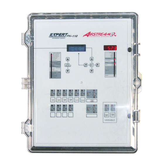
- Page 1 EXPERT PN110 Temperature controller User’s Manual...
- Page 2 Every effort has been made to ensure that this manual is complete, accurate and up- to-date. The information contained in it is however subject to change without notice due to further developments. EXPERT PN110 rev.23...
-
Page 3: Table Of Contents
15.2. Relay Assignment Worksheet ......42 6.3.1. Principle of Operation .......... 20 15.3. Installation Setup Worksheet ......43 6.3.2. Settings ............. 20 INDEX ................44 6.3.3. Actuator Reset ........... 21 6.3.4. Inlet Calibration ..........22 6.3.5. Opening Compensations ........22 EXPERT PN110 rev.23... -
Page 4: Introduction
Refer to the end of this manual to con- When the service disconnecting means nect the sensors and loads. cannot be locked, securely fasten a prominent warning device, such as a tag, to the service panel. EXPERT PN110 rev.23... -
Page 5: Main Features
To extend a sensor: Use a shielded cable of ing rooms. outside diameter between 0.245 and 0.260 in (6.22 and 6.60 mm) (the cable dimensions EXPERT PN110 rev.23... -
Page 6: 0-10V Output Connection
INLET OPEN Turns on when the inlet is opening CLOSE Turns on when the inlet closing FAN STAGE 1-8 Turns on when fan stage 1-8 is ON HEATERS 1-3 Turns on when heater 1-3 is ON EXPERT PN110 rev.23... -
Page 7: Installation Setup
If the password entered is incorrect, an error 1. LCD Contrast » message “Wrong Password” is displayed. Once the time and date have been adjusted, the notifi cation message disappears, the sys- • Changing the Installer Password: EXPERT PN110 rev.23... - Page 8 Use Interlock? — Select "Yes" if you want the the air inlet beyond the activation tempera- natural ventilation curtains to close while the Number of Heater Stages — Enable the proper EXPERT PN110 rev.23...
-
Page 9: Rh Compensation Setup
Mist on Low % RH — The controller can acti- static pressure vate misting outputs when humidity levels are T°/SP avg temperature & static pressure too low. Select “Yes” to use this compensa- T°/I1 avg temperature & inlet position tion method. EXPERT PN110 rev.23... -
Page 10: Water Meter Calibration
3. Proceed in similar fashion to assign relays desired probe. *Only the probes that have been to each heating stage in use. activated are displayed (section 4.7.1). 3. Select what probe(s) are used to measure the average temperature in the room. EXPERT PN110 rev.23... - Page 11 Timer — If timer-based relays are assigned to some fan stages set the “On Time” and the 2. Put a check mark to identify the relay used “Off Time” of the timer. to open or to close the air inlet. EXPERT PN110 rev.23...
- Page 12 2. Put a check mark to identify the relay(s) *A password is required to access this menu (sec. used by the soaking output. 4.2). Backup Relays 12345678901234 2. Put a check mark to identify the relay used by the backup box. EXPERT PN110 rev.23...
-
Page 13: Night Settings
*Accessible if a variable fan output is used in minimum ventilation (sec. 6.1). Detect Lo Temp? — Select "Yes" for the con- troller to monitor low temperature alarms during the clean mode. EXPERT PN110 rev.23... -
Page 14: Temperature Settings
Press the Edit key then press the outside temperature sensor is enabled in section the down-arrow key to turn it Off. 4.7 and if the curtain compensation is enabled in the Installation Setup (section 4.5). EXPERT PN110 rev.23... -
Page 15: Modifying Curve Points
*Accessible if the temperature curve is currently to be used in minimum ventilation. running. On Time / Cycle Time — If the variable out- put is used in minimum ventilation, set its minimum ventilation timer properly (On Time and Cycle Time). EXPERT PN110 rev.23... -
Page 16: Min Ventilation Curve
(fan speed & days). Use the down- arrow key to scroll each point of the curve. The curve status fl ashes on the display. Press the Edit key then press the down-arrow key to turn it Off. EXPERT PN110 rev.23... -
Page 17: Fan Stages
(On and Off Times). This is 0.3°F useful to activate misting units in timer mode Room T° V1 Bandwidth while a specifi c fan stage is active. Refer to section 4.7.4 to enable timer-based relays. EXPERT PN110 rev.23... -
Page 18: Settings
Var1 & Var2 bandwidth — Set the number of degrees required for variable fans to reach their full speed in stages 1 and 2. If the “Outside temperature compensation” function is used, set these bandwidths separately for winter and for summer (see sec. 4.5). EXPERT PN110 rev.23... -
Page 19: 0-10V Ventilation Outputs
(this parameter must be set to a greater value than the start temperature). Stop T° Start T° Avg T° Stop at — This is the temperature below of 0-10V T° which the 0-10V output stops. output probes EXPERT PN110 rev.23... -
Page 20: Air Inlets
Set this position to the Opening desired value. Bandwidth 5.0 °F Total open 2:00 Under Run T. 2 sec Min Vent — This is the position of the air inlet during the “On Time” portion of a minimum ventilation cycle. EXPERT PN110 rev.23... -
Page 21: Actuator Reset
Set the outside temperature below which inlet resets are forbidden (this includes manual resets). *This parameter is accessible if an outside temperature sensor is enabled (see sec- tion 4.7.1). EXPERT PN110 rev.23... -
Page 22: Inlet Calibration
“Minimum” parameter on screen. Once pensation is applied. the “Yes” answer is posted, the controller shows the word "Save" for 5 seconds and then displays "No" again; the maximum position has now been saved. 4. Once the calibration is EXPERT PN110 rev.23... -
Page 23: Static Pressure Set Points
(sec. 4.5 and 4.7.1). SP Set points Low SP .000"WC High SP .100"WC 2. Set the following parameters: Low / High Set Points — Set the low and high static pressure set points to the desired value. EXPERT PN110 rev.23... -
Page 24: Natural Ventilation
fl eeting temperature changes. Set the wind delay to the desired value. Purge Cycle — Select how much time sepa- rates 2 de-icing/purge cycles. This parameter is common to all curtains and it can be ad- justed from 5 to 540 minutes. EXPERT PN110 rev.23... -
Page 25: Curtain Compensation
If the room temperature increases suddenly will open and the shutoff fans will restart while being in natural ventilation and exceeds after the inlets are in position the security limit (Hi T° Restart ), the con- EXPERT PN110 rev.23... -
Page 26: Stir Fans
Set the on and off times of 0.5°F T° differ- the stir fan timer. ence Max T° between difference 2 probes EXPERT PN110 rev.23... -
Page 27: Misting Output
The maximum temperature ment the controller enters in clean mode (1 must be at least 0.5°F (0.3°C) greater than to 100 cycles). the ON TEMP. Min On Time OFF T° ON T° Max T° T° EXPERT PN110 rev.23... -
Page 28: Icing
The de-icing cycle begins when the outdoor temperature is below the start temperature and stops when outdoor temperature is above the stop temperature. You can set any temperature within the range which varies EXPERT PN110 rev.23... -
Page 29: Heating
The 0-10V heater start at their minimum inten- sity when the temperature falls below the start temperature of the output. The intensity of the heater increases as the temperature decreases; the maximum intensity is reached when the temperature falls below the Max. Temperature EXPERT PN110 rev.23... -
Page 30: Brooder Heater
Hi Fire brooder steps. Differential — Select the number of degrees below the Start Temperature at which the the brooder heater reaches its maximum EXPERT PN110 rev.23... -
Page 31: 0-10V Brooder Heater
Brooder Heater ii) Certain restrictions apply to reduce the Curve risk of errors: Curve Stat - The highest possible day number is 450. - Decreasing day numbers are not allowed. EXPERT PN110 rev.23... -
Page 32: Clock Outputs
Stop Time (e.g. 8h30AM) (e.g. 9h00AM) time at which each cycle starts then set the moment at which each cycle ends. Time Clock: Output Status Start/Run Mode Cycle Run Time Time (e.g. 30m:15s) Start Time (e.g. 8h30AM) EXPERT PN110 rev.23... -
Page 33: Rh Compensation
RH set point of the misting timer. Heater Compensation ON Time Time Min On Time(s) Max On Time(s) Cycle Cycle Time 300sec Time Mist Shutoff Mist on Lo %RH Lo SetPoint On Time 30sec Off Time 240sec EXPERT PN110 rev.23... -
Page 34: Alarms
48 hours ceeds the high temperature alarm setting, in a row (no consumption alarm can be a high temperature alarm is set off. When detected within this 48-hour delay): the average room temperature decreases EXPERT PN110 rev.23... -
Page 35: Alarm Settings
To disable this monitoring function, decrease the parameter value until the word “Off ” is displayed. *This parameter is accessible if the water meter is enabled (sec. 4.7.1). Refer to the previous section to get more information about this alarm limit. EXPERT PN110 rev.23... -
Page 36: Monitoring Functions
Today’s Min / Max 60 Max the selected feeder. Press the Edit key once again to validate. The "Yes" answer switches to "No" once again, this means the history has now been cleared. EXPERT PN110 rev.23... -
Page 37: Water Consumption Daily History
» 3. Last 48Hr/Hd humidity levels that were measured every hour for the past 7 days. * This history is ac- cessible if the inside humidity sensors is enabled Water Consumption (sec. 4.6.1). L.24Hr/Hd 0.000Gal P.24Hr/Hd 0.000Gal EXPERT PN110 rev.23... -
Page 38: Animal Age & Count
Initial Size Dead Yesterday culled and marketed animals for the past 7 days. Cul. Yesterday These values cannot be modifi ed. Dead 2 Days ago 0 Cul. 2 Days ago 0 Mark 2 Days ago 0 EXPERT PN110 rev.23... -
Page 39: Technical Specifications
1 1/2HP (1120W) @ 240Vac, 10A max Fuse on variable outputs ............ 15A slow blow The room temperature where the con- troller is located must always remain between 32 °F and 104 °F (0 °C and 40 °C). EXPERT PN110 rev.23... -
Page 40: Transfer Menu
fi les that are located at the root of MENU SELECT buttons for 5 seconds the USB drive. It cannot access any to exit from the transfer menu. sub-directory! Remove the USB drive from the connector when the transfer is over! EXPERT PN110 rev.23... -
Page 41: Worksheet
EXPERT PN110 15. WORKSHEET CLIENT Name: ___________________________________________________________ Address: ___________________________________________________________ ___________________________________________________________ ___________________________________________________________ City: ___________________________________________________________ Tel.: ___________________________________________________________ Fax: ___________________________________________________________ E-mail: ___________________________________________________________ INSTALLER Name: ___________________________________________________________ Address: ___________________________________________________________ ___________________________________________________________ ___________________________________________________________ City: ___________________________________________________________ Tel.: ___________________________________________________________ Fax: ___________________________________________________________ E-mail: ___________________________________________________________ EXPERT PN110 rev.23... -
Page 42: Probe Assignment Worksheet
Curtain 1 Close Curtain 1 Close Cooling output Cooling output Soaking Soaking Stir Fan Stir Fan Clock 1 Clock 1 Clock 2 Clock 2 Backup relay box Backup relay box Brooder Brooder Brooder Hi Fire Brooder Hi Fire EXPERT PN110 rev.23... -
Page 43: Installation Setup Worksheet
Variable output 2 Minimum Speed _______ (10-100%) Variable output 2 Motor Curve _______ (1-10) Outdoor compensation on variable outputs? ___Yes ____No Digit display ___T° ____Stat.Pressure (SP). __Inlet 1 (I1) ___T°&SP ___T°&I1 ____SP&I1 8. PASSWORD (sec. 4.2) Installer password ______ _______ ______ EXPERT PN110 rev.23... -
Page 44: Index
Output status LEDs Fan stages (0-10V fans) Installation setup 8–13 Information on screen 9 Activation 8 Location of the controls 6 Location 6 Operation & settings 19 Mounting instructions 5 Meaning 6 Probe assignment 10 Liters 7 EXPERT PN110 rev.23... - Page 45 Winter & summer T° 18 Settings 26 Wiring 5 Summer & winter T° 18 Worksheets 40 Parameter adjustment 6 Password Technical specifi cations 38 Entering/changing the password 7 Temperature Probe Average room temperature Activation 9 Assignment 10–13 EXPERT PN110 rev.23...
- Page 46 EXPERT PN110 NOTES EXPERT PN110 rev.23...
- Page 47 EXPERT PN110 NOTES EXPERT PN110 rev.23...
- Page 48 M 890-00001 rev.23 REV. 17...
Need help?
Do you have a question about the EXPERT PN110 and is the answer not in the manual?
Questions and answers