Danfoss H1P Series Service Manual
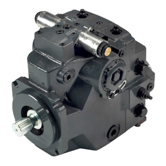
Axial piston single pumps
Hide thumbs
Also See for H1P Series:
- Electrical installation (12 pages) ,
- Technical information (68 pages)
Table of Contents
Advertisement
Quick Links
Advertisement
Table of Contents

Related Manuals for Danfoss H1P Series


Summary of Contents for Danfoss H1P Series
- Page 1 Service Manual H1P 069—H1P 250 Axial Piston Single Pumps www.danfoss.com...
- Page 2 0504 removed pressure limiter screens January 2020 Corrected the A/B port size for 115/130 frame 0402 December 2018 Major clean-up revision. 0401 July 2008- May 2018 Various changes. 0201-0308 September 2007 First edition. 0101 © Danfoss | September 2020 AX152886482551en-000504...
-
Page 3: Table Of Contents
H1P 069—H1P 250 Axial Piston Single Pumps Contents Introduction Hydrostatics Servicing Overview..............................5 General Servicing Instructions..............................5 Safety Precautions....................................6 Symbols used in Danfoss literature............................7 General description of H1 family hydrostatic pumps......................7 Design........................................8 H1 Single Pumps Closed Circuit Pictorial Diagram......................10 H1 system schematic..................................10 Operation Pressure Limiter Valves................................ - Page 4 Mechanical Neutral Adjustment...............................40 Unintended Machine Movement............................40 Minor Repair Angle sensor on EDC Repair...............................47 EDC with Angle Sensor Repair..............................48 Torque Chart Fasteners and Plugs..................................61 Fastener Size and Torque Chart..............................62 Plug Size and Torque Chart................................ 63 © Danfoss | September 2020 AX152886482551en-000504...
-
Page 5: Hydrostatics Servicing Overview
A worldwide network of Danfoss Global Service Partners is available for major repairs. Danfoss trains and certifies Global Service Partners on a regular basis. You can locate your nearest Global Service Partner using the distributor locator at http://www.danfoss.com. -
Page 6: Safety Precautions
Use proper safety equipment, including safety glasses, at all times. Hazardous Material Hydraulic fluid contains hazardous material. Avoid prolonged contact with hydraulic fluid. Always dispose of used hydraulic fluid according to state, and federal environmental regulations. © Danfoss | September 2020 AX152886482551en-000504... -
Page 7: Symbols Used In Danfoss Literature
The flow rate is proportional to the pump input speed and displacement. The latter is infinitely adjustable between zero and maximum displacement. H1 pumps can be used together in combination with other Danfoss pumps and motors in the overall hydraulic system. -
Page 8: Design
More compact and lightweight • Improved reliability and performance Go to the Danfoss website or applicable product catalog to choose the components that are right for your complete closed circuit hydraulic system. Design Danfoss H1 closed circuit piston pumps convert input torque into hydraulic power. The input shaft transmits rotational force to the cylinder block. - Page 9 The motor case drain can connect to the lower drain port on the pump housing or it can tee into the case drain line upstream of the heat exchanger. A heat exchanger with bypass valve cools the case drain fluid before it returns to the reservoir. © Danfoss | September 2020 AX152886482551en-000504 | 9...
-
Page 10: H1 Single Pumps Closed Circuit Pictorial Diagram
Charge Check/High Pressure Relief Valve P104 464E H1 system schematic System schematic H1 pump and H1 motor with EDC M3 L1 L2 MA F00B F00A max. min. L3 L4 max. 3 bar [43.5 psi] P003 424 10 | © Danfoss | September 2020 AX152886482551en-000504... - Page 11 The schematic above shows the function of a hydrostatic transmission using an H1 axial variable displacement pump with electric proportional displacement control (EDC) and an H1 bent axis variable displacement motor with electric proportional control (L*) and integrated loop flushing device. © Danfoss | September 2020 AX152886482551en-000504 | 11...
-
Page 12: Operation
HPRV valve is always factory set above the setting of the pressure limiter. The system pressure shown in the order code for pumps with only HPRV is the HPRV setting. 12 | © Danfoss | September 2020 AX152886482551en-000504... -
Page 13: Hprv/Charge Check Valve Sectional View
The HPRV valve also provides a loop bypass function when each of the two HPRV hex plugs are mechanically backed out 3 full turns. Engaging the bypass function hydraulically connects both A & B © Danfoss | September 2020 AX152886482551en-000504 | 13... -
Page 14: System Schematic For Single Pump
A serviceable 125 μm screen is located in the supply line immediately before the control porting spool. Under some circumstances, such as contamination, the control spool could stick and cause the pump to stay at some displacement. 14 | © Danfoss | September 2020 AX152886482551en-000504... -
Page 15: Edc Operation
When the control input signal is either lost or removed, or if there is a loss of charge pressure, the spring- loaded servo piston will automatically return the pump to the neutral position. © Danfoss | September 2020 AX152886482551en-000504 | 15... -
Page 16: Manual Override (Mor)
Simultaneously the swashplate movement is fed back to the control spool providing proportionality between shaft rotation on the control and swash-plate rotation. The MDC changes the pump displacement between no flow and full flow into opposite directions. 16 | © Danfoss | September 2020 AX152886482551en-000504... -
Page 17: Mdc Operation
Bowden cable or a joystick back to neutral position. It is not applicable for any limitation of the Bowden cable stroke, except the applied torque to the shaft will never exceed 20 N•m. © Danfoss | September 2020 AX152886482551en-000504 | 17... -
Page 18: Mdc Torque
IP67 / IP69K with mating connector Electrical protection class Case Gauge Port M14 The drain port should be used when the control is mounted on the unit’s bottom side to flush residual contamination out of the control. 18 | © Danfoss | September 2020 AX152886482551en-000504... -
Page 19: Operating Parameters
All pressure limits are differential pressures referenced to low loop (charge) pressure. Subtract low loop pressure from gauge readings to compute the differential. © Danfoss | September 2020 AX152886482551en-000504 | 19... -
Page 20: Servo Pressure
Operation with case pressure in excess of stated limits may damage seals, gaskets, and/or housings, causing external leakage. Performance may also be affected since charge and system pressure are additive to case pressure. 20 | © Danfoss | September 2020 AX152886482551en-000504... -
Page 21: External Shaft Seal Pressure
The minimum temperature relates to the physical properties of component materials. Size heat exchangers to keep the fluid within these limits. Danfoss recommends testing to verify that these temperature limits are not exceeded. Viscosity For maximum efficiency and bearing life, ensure the fluid viscosity remains in the recommended range. -
Page 22: Technical Specifications
The housing must always be filled with hydraulic fluid. Recommended mounting for a multiple pump stack is to arrange the highest power flow towards the input source. Consult Danfoss for nonconformance to these guidelines. Auxiliary cavity pressure Auxiliary cavity pressure will be inlet pressure with internal charge pump or case pressure with external charge supply. -
Page 23: Fluid Specification
115°C [240°F] Maximum Intermittent Cold start = Short term t > 3 min, p ≤ 50 bar [725 psi], n ≤ 1000 min-1 (rpm). At the hottest point, normally case drain port. © Danfoss | September 2020 AX152886482551en-000504 | 23... -
Page 24: Fluid And Filter Maintenance Recommendations
Hydraulic fluid contains hazardous material. Avoid contact with hydraulic fluid. Always dispose of used hydraulic fluid according to state and federal environmental regulations. For further information see Danfoss publication Technical Information, Hydraulic Fluids and Lubricants, BC0000093. Filtration System To prevent premature wear, ensure only clean fluid enters the hydrostatic transmission circuit. A filter capable of controlling the fluid cleanliness to ISO 4406 class 22/18/13 (SAE J1165) or better, under normal operating conditions, is recommended. - Page 25 = 75 (β ≥ 10) Efficiency β (charge pressure filtration) 15-20 β = 75 (β ≥ 2) Efficiency β (suction and return line filtration) 35-45 100 – 125 µm Recommended inlet screen mesh size © Danfoss | September 2020 AX152886482551en-000504 | 25...
-
Page 26: Pressure Measurements
When testing system pressures, calibrate pressure gauges frequently to ensure accuracy. Use snubbers to protect gauges. The drawing and following table show the port locations and gauge sizes needed. Port locations System Port B System Port A G302 D065 P106033 H1P Ports Information 26 | © Danfoss | September 2020 AX152886482551en-000504... - Page 27 Servo pressure M4/M5 7/16-20 UNF 2B 3/16 internal hex wrench size Charge pressure (pre integrated filter) M6 9/16-18 UNF 2B 1/4 internal hex wrench size Gauge size (All) 50 bar [1000 psi] © Danfoss | September 2020 AX152886482551en-000504 | 27...
-
Page 28: Initial Startup Procedures
Let the engine run for a minimum of 30 seconds at low idle to allow the air to work itself out of the system. 12. Check for leaks at all line connections and listen for cavitation. 28 | © Danfoss | September 2020 AX152886482551en-000504... - Page 29 Normal charge pressure fluctuation may occur during forward and reverse operation. 19. Check that the reservoir is full and remove charge pressure gauge. The pump is now ready for an operation. © Danfoss | September 2020 AX152886482551en-000504 | 29...
-
Page 30: Troubleshooting
Filter bypass indicator switch Filter bypass indicator switch is indicating wrong bypass Check/replace filter switch. • situation. Open resistance ≥ 510 Ω • Closed resistance ≤ 122 Ω 30 | © Danfoss | September 2020 AX152886482551en-000504... -
Page 31: Neutral Difficult Or Impossible To Find
Check for torn/missing servo seals. Replace and retest. Only decaying stroking the pump. a Danfoss Authorized Service Center may remove the servo piston without voiding the warranty. Bypass function open Open bypass will cause one or both directions to be Close bypass function. -
Page 32: System Will Not Operate In Either Direction
Control orifices are blocked. Clean control orifices. Pump control screens Control screens are blocked. Replace control screens. Only a Danfoss Authorized Service Center may remove the unit’s endcap without voiding the warranty. Bypass function open If bypass function is open, the system loop will be Close bypass valves. - Page 33 Control orifices are plugged. Clean control orifices. orifices Contaminated control EDC supply screen is plugged. Replace control screens. Only a Danfoss Authorized Service screens Center may remove the unit’s endcap without voiding the warranty. Pump inlet vacuum Inlet vacuum is too high resulting in reduced system Measure charge inlet vacuum.
-
Page 34: Adjustments
2. Install a 10 bar [100 psi] gauge at case drain port L2 or L4. The table below shows the acceptable actual pump charge pressure range for some nominal CPRV settings (refer to model code located on serial number plate). 34 | © Danfoss | September 2020 AX152886482551en-000504... -
Page 35: Pressure Limiter Adjustment
Pumps with only HPRV valves no longer contain pressure limiter screens and retainers. To convert such pumps to those with pressure limiter valves, please contact your Danfoss service partner. H1P Base Models with pressure setting option B include PL screens and retainers. - Page 36 The model code on the serial plate gives the factory setting of the PL (Pressure Limiter). The PL setting is referenced to charge pressure. Subtract charge pressure from system pressure gauge readings to compute the effective PL setting. 8. Repeat steps 4. and 5. until you reach the desired PL setting. 36 | © Danfoss | September 2020 AX152886482551en-000504...
-
Page 37: Engaging The Bypass Function
Limiting displacement requires clockwise adjustment of the limiting screw. Caution Before adjusting the displacement limiter, mark the position of the servo cylinder. Be sure the servo cylinder does not turn when setting the displacement limiter locknut. © Danfoss | September 2020 AX152886482551en-000504 | 37... -
Page 38: Control Neutral Adjustment
If adjustment fails to give satisfactory results, you may need to replace the control or coils. See Minor repair for details. 38 | © Danfoss | September 2020 AX152886482551en-000504... - Page 39 Illustration shows how cam on adjusting pin rotates to adjust for neutral position after pump is re- installed. 6. Rotate the neutral adjusting screw clockwise until the pressure increases on the gauge. Note the angular position of the wrench. © Danfoss | September 2020 AX152886482551en-000504 | 39...
-
Page 40: Mechanical Neutral Adjustment
Secure the machine or disable/disconnect the mechanism while servicing to protect against unintended movement. Pump Setup The figure below shows the locations of system and gauge ports you use when adjusting the servo neutral postion. 40 | © Danfoss | September 2020 AX152886482551en-000504... - Page 41 5. If using a PWM signal to set mechanical neutral, connect the control solenoids C1 and C2 to the signal source. Ensure the source supplies no current to the solenoids until required in the following procedure. © Danfoss | September 2020 AX152886482551en-000504 | 41...
- Page 42 (M4/M5) and the control solenoids (C1/C2) are opposite. 9. Remove all gauges and replace gauge port plugs. You can find wrench sizes and plug torques in the Plug Size and Torque Chart on page 63. 42 | © Danfoss | September 2020 AX152886482551en-000504...
-
Page 43: Minor Repair
D250 D025A 5 mm 13.5 N•m [10 lbf•ft] D025 D025A D050 (3X) 4 mm D084 5 N•m [4 lbf•ft] D150 F100 (2X) 3 mm 2.5 N•m [1.8 lbf•ft] D300 (2X) P106 052E © Danfoss | September 2020 AX152886482551en-000504 | 43... - Page 44 Inspect the machined surfaces on the control and top of the pump. If you find any nicks or scratches, replace the component. 4. Lubricate new O-ring (D025A) using petroleum jelly and install. 44 | © Danfoss | September 2020 AX152886482551en-000504...
- Page 45 D025 D050 (3X) 4 mm D025A D025A D050 (3X) 4 mm MDC Repair Legend: D80 – Solenoid D81 – O-ring D098 – Retaining ring D750 – Neutral start switch D751 – O-ring © Danfoss | September 2020 AX152886482551en-000504 | 45...
- Page 46 Ensure you install dowel pins (D300) in housing before installing control. The pump will lose control, causing a potentially hazardous situation. If a feedback pin comes off during operation, ensure the feedback pin is properly torqued before continuing with reassembly. 46 | © Danfoss | September 2020 AX152886482551en-000504...
-
Page 47: Angle Sensor On Edc Repair
1.85 N•m [1.36 lbf•ft]. 9. Position protection cover on control housing over sensor. 10. Using a 4 mm internal hex wrench, fasten protection cover with screws (D767). Torque screws to 1.85 N•m [1.36 lbf•ft]. © Danfoss | September 2020 AX152886482551en-000504 | 47... -
Page 48: Edc With Angle Sensor Repair
5. Ensure assembly fixture is positioned over the linkage spring in EDC center. 6. Position the control on the pump housing and ensure that feedback pin on swashplate is positioned properly in control arm. 48 | © Danfoss | September 2020 AX152886482551en-000504... - Page 49 Automotive Control Repair Drain pump completely before removing control. Possible erratic pump operation. Do not allow metal fragments to fall into control housing. Do not fail to install screen. © Danfoss | September 2020 AX152886482551en-000504 | 49...
- Page 50 5. Use a 5 mm internal hex to remove two screws (D674) and remove shield (D672). 6. Use a 5 mm internal hex to remove six screws (D250) and remove control from pump. 50 | © Danfoss | September 2020 AX152886482551en-000504...
- Page 51 3. If previously removed, install orifices using a 3 mm internal hex wrench and torque to 2.5 N•m [1.8 lbf•ft]. 4. Install a new gasket (D150). 5. Install the control module and six cap screws (D250). © Danfoss | September 2020 AX152886482551en-000504 | 51...
- Page 52 8. After you remove the shaft, take care not to move or jar the pump. Reassembly can be difficult if the internal components move while the shaft is out. 9. Remove snap-ring (J300). 10. Press bearing (J150) from shaft. 52 | © Danfoss | September 2020 AX152886482551en-000504...
- Page 53 120 mm 115/130 [4.72 in] 147/165 75.6 mm 82 mm 210/250 [2.97 in] 078/089/100 [3.23 in] 4.4 mm 7 mm [0.17 in] [0.28 in] P106492 11. Install the remaining snap ring (J200). © Danfoss | September 2020 AX152886482551en-000504 | 53...
- Page 54 9. Use a 24 mm wrench to hold the plug in place and install the replacement filter. Hand tighten filter till it contacts O-ring, then tighten 1/2 turn further. 10. Start the prime mover. Cycle the pump through normal machine operation and check for leaks. 54 | © Danfoss | September 2020 AX152886482551en-000504...
- Page 55 Charge Pump Repair (Removable Auxiliary Pad) If an auxiliary pump is attached, remove auxiliary pump and coupling before servicing charge pump. Position pump with front shaft pointing downward. Attach securely to a proper work stand. © Danfoss | September 2020 AX152886482551en-000504 | 55...
- Page 56 Charge Pump Repair (Integrated Auxiliary Pad) If an auxiliary pump is attached, remove auxiliary pump and coupling before servicing charge pump. Position pump with front shaft pointing downward. Attach securely to a proper work stand. 56 | © Danfoss | September 2020 AX152886482551en-000504...
- Page 57 2. Install valve plate (S250) in the same orientation as removed. 3. Lubricate and install charge pump gearset (S100) and outer ring (S150). 4. Install charge pump coupling (K200). 5. Install pressure-balance plate (S200) in the same orientation as removed. © Danfoss | September 2020 AX152886482551en-000504 | 57...
- Page 58 2. Inspect the sealing surfaces in the pump for nicks or scratches, check the valves for damage. 3. Replace any damaged components. 4. Remove and discard the O-rings (L060) and backup rings (L068). 58 | © Danfoss | September 2020 AX152886482551en-000504...
- Page 59 Pumps with only HPRV valves no longer contain pressure limiter screens and retainers. To convert such pumps to those with pressure limiter valves, please contact your Danfoss service partner. H1P Base Models with pressure setting option B include PL screens and retainers.
- Page 60 5. Replace pressure limiter valve and torque to 70 N·m [52 lbf·ft]. 6. Operate pump at full range of controls to ensure proper machine operation. Pressure Limiter Adjustment on page 35 for adjustment instructions. 60 | © Danfoss | September 2020 AX152886482551en-000504...
-
Page 61: Torque Chart
Charge pressure adjusting screw V022 Charge pressure locking nut K400 Rear cover / auxiliary pad mounting bolt V010 Charge pressure cartridge L150 High pressure relief valve T015 Filter mounting bolt P106 066E © Danfoss | September 2020 AX152886482551en-000504 | 61... -
Page 62: Fastener Size And Torque Chart
Charge pressure cartridge 22 mm 52 N•m [38 lbf•ft] V020 Charge pressure adjusting screw 4 mm internal hex V022 Charge pressure locking nut 13 mm 12 N•m [9 lbf•ft] 19 mm (210/250) 62 | © Danfoss | September 2020 AX152886482551en-000504... -
Page 63: Plug Size And Torque Chart
12 N•m [9 lbf•ft] G250 9/16–18 1/4 internal hex 40 N•m [29.5 lbf•ft] G300 9/16–18 3/16 internal hex 40 N•m [29.5 lbf•ft] G302 5/16–24 UNF 1/8 internal hex 5 N•m [4 lbf•ft] © Danfoss | September 2020 AX152886482551en-000504 | 63... - Page 64 Phone: +86 21 2080 6201 Danfoss can accept no responsibility for possible errors in catalogues, brochures and other printed material. Danfoss reserves the right to alter its products without notice. This also applies to products already on order provided that such alterations can be made without subsequent changes being necessary in specifications already agreed.
Need help?
Do you have a question about the H1P Series and is the answer not in the manual?
Questions and answers