Table of Contents
Advertisement
Advertisement
Table of Contents

Related Manuals for PaloAlto Networks PA-5200 Seriesp


Summary of Contents for PaloAlto Networks PA-5200 Seriesp
- Page 1 PA-5200 Series Next-Gen Firewall Hardware Reference docs.paloaltonetworks.com...
- Page 2 Contact Informaon Corporate Headquarters: Palo Alto Networks 3000 Tannery Way Santa Clara, CA 95054 www.paloaltonetworks.com/company/contact-support.html About the Documentaon • For the most recent version of this guide or for access to related documentaon, visit the Technical Documentaon portal docs.paloaltonetworks.com. • To search for a specific topic, go to our search page docs.paloaltonetworks.com/search.html. •...
-
Page 3: Table Of Contents
Table of Contents Before You Begin....................5 Upgrade/Downgrade Consideraons for Firewalls and Appliances........ 6 Tamper Proof Statement......................7 Third-Party Component Support..................... 8 Product Safety Warnings......................9 PA-5200 Series Firewall Overview..............13 PA-5200 Front Panel........................ 14 PA-5200 Back Panel.........................17 Install the PA-5200 Series Firewall in an Equipment Rack....19 Install the PA-5200 Series Firewall in a 19-inch Equipment Rack.........20 Install the Four-Post Rack Kit on a PA-5200 Series Firewall.......... - Page 4 Table of Contents PA-5200 Series Next-Gen Firewall Hardware Reference 2021 Palo Alto Networks, Inc. ©...
-
Page 5: Before You Begin
Before You Begin Read the following topics before you install or service a Palo Alto Networks next- ® generaon firewall or appliance. The following topics apply to all Palo Alto Networks firewalls and appliances except where noted. > Upgrade/Downgrade Consideraons for Firewalls and Appliances >... -
Page 6: Upgrade/Downgrade ConsideraOns For Firewalls And Appliances
Before You Begin Upgrade/Downgrade Consideraons for Firewalls and Appliances The following table lists hardware features that have upgrade or downgrade impact. Make sure you understand all upgrade/downgrade consideraons before you upgrade or downgrade from the specified version of PAN-OS. Feature Release Upgrade Consideraons Downgrade... -
Page 7: Tamper Proof Statement
Before You Begin Tamper Proof Statement To ensure that products purchased from Palo Alto Networks were not tampered with during shipping, verify the following upon receipt of each product: • The tracking number provided to you electronically when ordering the product matches the tracking number that is physically labeled on the box or crate. -
Page 8: Third-Party Component Support
Before You Begin Third-Party Component Support Before you consider installing third-party hardware, read the Palo Alto Networks Third-Party Component Support statement. PA-5200 Series Next-Gen Firewall Hardware Reference 2021 Palo Alto Networks, Inc. ©... -
Page 9: Product Safety Warnings
Before You Begin Product Safety Warnings To avoid personal injury or death for yourself and others and to avoid damage to your Palo Alto Networks hardware, be sure you understand and prepare for the following warnings before you install or service the hardware. You will also see warning messages throughout the hardware reference where potenal hazards exist. - Page 10 Before You Begin • (All Palo Alto Networks appliances with two or more power supplies) Cauon: Shock hazard Disconnect all power cords (AC or DC) from the power inputs to fully de-energize the hardware. French Translaon: (Tous les appareils Palo Alto Networks avec au moins deux sources d’alimentaon) Débranchez tous les cordons d’alimentaon (c.a.
- Page 11 Before You Begin The following applies only to Palo Alto Networks firewalls that support a direct current (DC) power source: French Translaon: Les instrucons suivantes s’appliquent uniquement aux pare-feux de Palo Alto Networks prenant en charge une source d’alimentaon en courant connu (c.c.): •...
- Page 12 Before You Begin • Install the firewall DC ground cable only as described in the power connecon procedure for the firewall that you are installing. You must use the American wire gauge (AWG) cable specified and torque all nuts to the torque value specified in the installaon procedure for your firewall.
-
Page 13: Pa-5200 Series Firewall Overview
PA-5200 Series Firewall Overview The Palo Alto Networks PA-5200 Series next-generaon firewalls are designed ® for data center and internet gateway deployments. This series is comprised of the PA-5220, PA-5250, PA-5260, and PA-5280 firewalls. These models provide flexibility in performance and throughput levels to help you meet your deployment requirements. -
Page 14: Pa-5200 Front Panel
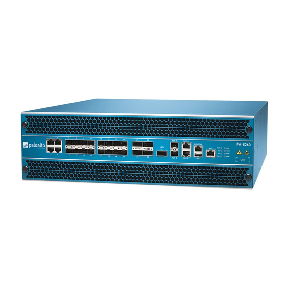
PA-5200 Series Firewall Overview PA-5200 Front Panel The following image shows the front panel of the PA-5200 Series firewall and the table describes each front panel component. The only differences between the PA-5220 (shown), PA-5250, PA-5260, and PA-5280 panels is the model name and the Ethernet port speeds as described in the table. - Page 15 PA-5200 Series Firewall Overview Item Component Descripon PA-5200 Series firewalls in a high availability (HA) configuraon as follows: • In an acve/passive configuraon, this port is for HA2 (data link). • In an acve/acve configuraon, you can configure this port for HA2 and/or HA3.
- Page 16 PA-5200 Series Firewall Overview Item Component Descripon HA1-A and HA1-B Two RJ-45 10/100/1000Mbps ports for high- availability control (HA1). CONSOLE port Use this port to connect a management computer to the firewall using a 9-pin serial to (RJ-45) RJ-45 cable and terminal emulaon soware. The console connecon provides access to firewall boot messages, the Maintenance Recovery Tool (MRT), and the command line...
-
Page 17: Pa-5200 Back Panel
PA-5200 Series Firewall Overview PA-5200 Back Panel The following image shows the back panel of PA-5200 Series firewalls and the table describes each back-panel component. The only difference between PA-5200 Series firewall back panels is the power supply type installed—they each can have two AC or two DC power supplies. The image shows a PA-5220 firewall with AC power supplies. - Page 18 PA-5200 Series Firewall Overview PA-5200 Series Next-Gen Firewall Hardware Reference 2021 Palo Alto Networks, Inc. ©...
-
Page 19: Install The Pa-5200 Series Firewall In An Equipment Rack
Install the PA-5200 Series Firewall in an Equipment Rack The PA-5200 Series next-generaon firewall ships with two rack-mount brackets for installaon in a two-post or four-post 19” equipment rack. If you install the firewall in a four-post rack, you can purchase and install the oponal four-post rack kit to secure the firewall to the back rack posts for addional support. -
Page 20: Install The Pa-5200 Series Firewall In A 19-Inch Equipment Rack
Install the PA-5200 Series Firewall in an Equipment Rack Install the PA-5200 Series Firewall in a 19-inch Equipment Rack The following procedure describes how to install the PA-5200 Series firewall in a two-post or four-post equipment rack. When installing the firewall in a two-post equipment rack, ensure that the rack is properly anchored and can support the weight of the installed equipment. -
Page 21: Install The Four-Post Rack Kit On A Pa-5200 Series Firewall
Install the PA-5200 Series Firewall in an Equipment Rack Install the Four-Post Rack Kit on a PA-5200 Series Firewall The following procedure describes how to install the oponal four-post rack kit (PAN-PA-5200- RACK4) to provide addional support to the back of the firewall. This kit supports rack depths from 23 to 32 inches (measured between the inner-parts of the vercal rails). - Page 22 Install the PA-5200 Series Firewall in an Equipment Rack screws (#10-32 x 3/4” or #12-24 x 1/2”) for your rack and torque to 25 in-lbs. Use cage nuts (not provided) to secure the screws if the rack has square holes. STEP 4 | Slide one back rack-mount bracket onto each of the two previously installed side rack- mount rails and secure the brackets to the back rack posts using four screws for each bracket...
-
Page 23: Connect Power To A Pa-5200 Series Firewall
Connect Power to a PA-5200 Series Firewall PA-5200 Series firewalls have either two AC or two DC power supplies (the second power supply is for redundancy). The firewall requires a 100-240VAC (50-60 Hz) or -40 to -60VDC power source, depending on the type of power supplies installed in the firewall (AC or DC).For more details on power requirements and power consumpon, PA-5200 Series Electrical Specificaons. -
Page 24: Connect Ac Power To A Pa-5200 Series Firewall
Connect Power to a PA-5200 Series Firewall Connect AC Power to a PA-5200 Series Firewall The following procedure describes how to connect AC power to a PA-5200 Series firewall with AC power supplies. To avoid injury to yourself or damage to your Palo Alto Networks hardware or the data ®... -
Page 25: Connect Dc Power To A Pa-5200 Series Firewall
Connect Power to a PA-5200 Series Firewall Connect DC Power to a PA-5200 Series Firewall The following procedure describes how to connect DC power to a PA-5200 Series firewall with DC power supplies. To avoid injury to yourself or damage to your Palo Alto Networks hardware or the data ®... - Page 26 Connect Power to a PA-5200 Series Firewall cable to the negave terminal. Repeat this step for the second DC power supply using separate posive and negave cables. 4. Replace the plasc covers over each DC power input. 5. Connect the two posive and two negave DC power cables to your power source, ensuring that you observe the correct polarity (posive to posive and negave to negave).
-
Page 27: Service The Pa-5200 Series Firewall
Service the PA-5200 Series Firewall The following topics describe how to interpret the PA-5200 Series firewall status LEDs and describes how to replace the serviceable components. > Interpret the LEDs on a PA-5200 Series Firewall > Replace the Air Intake Filters on a PA-5200 Series Firewall >... -
Page 28: Interpret The Leds On A Pa-5200 Series Firewall
Service the PA-5200 Series Firewall Interpret the LEDs on a PA-5200 Series Firewall The following table describes how to interpret the status LEDs on a PA-5200 Series firewall. Descripon Front Panel LEDs Power Supply (with black handle) PWR (Power) Green—The firewall is powered on. Off—The firewall is not powered on or an error occurred with the internal power system (for example, power is not within tolerance levels). - Page 29 Service the PA-5200 Series Firewall Descripon Red—One or more fans failed on one or both of the fan trays. To determine which fan tray has a failure, check the system log or check the LED on the fan trays. ALM (Alarm) Red—A hardware component failed, such as a power supply failure, a firewall failure that caused an HA failover, a drive failure, or hardware is overheang and the temperature is above the high...
- Page 30 Service the PA-5200 Series Firewall Descripon Power Supply (with red handle) • FAIL (Boom/DC LED) • Solid green—The power supply is operang normally. • Solid yellow—The power supply failed. This can also indicate a fan failure or overheang condion. • Blinking yellow and green (Alternang at 2:1 rao)—The power supply is at high temperature.
-
Page 31: Replace The Air Intake Filters On A Pa-5200 Series Firewall
Service the PA-5200 Series Firewall Replace the Air Intake Filters on a PA-5200 Series Firewall The air intake filters are a crical part of the firewall cooling system. These filters ensures that air entering the firewall does not contain debris. We recommend that you replace both filters (top and boom) every six months or less, depending on the environment where the firewall is located, to prevent a scenario where there is not enough air passing through the filters to keep the firewall from overheang. - Page 32 Service the PA-5200 Series Firewall STEP 3 | Install a new filter into the filter cover ensuring that you slide it under the filter cover cross bars. You can install the filter with either side facing up. STEP 4 | Replace the top filter cover and filter and turn the two thumb screws clockwise to secure the cover to the firewall.
-
Page 33: Replace A Fan Tray On A Pa-5200 Series Firewall
Service the PA-5200 Series Firewall Replace a Fan Tray on a PA-5200 Series Firewall PA-5200 Series firewalls have two fan trays and each fan tray contains four fans. If one fan on a fan tray fails, the LED on the fan tray turns red. When this occurs, immediately replace the fan tray to avoid service interrupon. -
Page 34: Replace A Power Supply On A Pa-5200 Series Firewall
Service the PA-5200 Series Firewall Replace a Power Supply on a PA-5200 Series Firewall PA-5200 Series firewalls have either two AC or two DC power supplies (the second power supply is for redundancy). If one power supply fails, you can replace it without service interrupon as described in the following procedures. -
Page 35: Replace A Dc Power Supply On A Pa-5200 Series Firewall
Service the PA-5200 Series Firewall STEP 5 | Connect the AC power cord to the power supply input and secure it to the power supply using the Velcro strap. STEP 6 | Connect the other end of the power cord to a grounded AC power source. The new power supply automacally powers on, the OK LED turns green, the FAIL LED turns off, and the power LED (PWR 1 or PWR 2) on the front of the firewall turns green. - Page 36 Service the PA-5200 Series Firewall STEP 5 | Remove the replacement power supply from the packaging and slide it into the empty power supply slot. Push the power supply all the way in unl the release lever clicks and secures the power supply.
-
Page 37: Replace A Drive On A Pa-5200 Series Firewall
Service the PA-5200 Series Firewall Replace a Drive on a PA-5200 Series Firewall The PA-5200 Series firewalls have two solid-state drives (SSDs) used for system files and system logs and two hard-disk drives (HDDs) used for network traffic log storage. Each drive pair is in a RAID 1 array so that if a drive fails, you can replace the failed drive (using the same model drive) without service interrupon. - Page 38 Service the PA-5200 Series Firewall Disk id Log1 Present model : ST2000NX0253 size : 1907729 MB status : failed Disk id Log2 Present model : ST2000NX0253 size : 1907729 MB status : active sync STEP 2 | Remove the failed drive from the RAID 1 array configuraon. In this example, run the following command to remove the Log1 drive from the array: admin@PA-5020>...
- Page 39 Service the PA-5200 Series Firewall STEP 5 | Install the replacement drive in the drive carrier. 1. Remove the replacement drive from the anstac bag and place it on an anstac surface. Place the failed drive next to the replacement drive with the connectors facing the same direcon.
- Page 40 Service the PA-5200 Series Firewall STEP 8 | Same model replacement drive only) Add the replacement drive (that is the same model as the failed drive) to the RAID 1 array: 1. Add the replacement drive to the RAID 1 array. In this example, run the following command to add the LOG 1 drive to the array: admin@PA-5020>...
- Page 41 Service the PA-5200 Series Firewall STEP 9 | Different model replacement drive only) Add the replacement drive (that is a different model than the failed drive) to the RAID 1 array: When you iniate the copy command as described in the following steps, logging stops and you cannot view logs unl the copy is complete and the disk pair shows Available.
-
Page 42: Replace A System Drive On A Pa-5200 Series Firewall
Service the PA-5200 Series Firewall status : not in use 4. Replace the other drive in the array so the drive models in the array are the same. In this example, physically remove the Log2 drive, remove it from the carrier, and then install the second replacement drive in the carrier. - Page 43 Service the PA-5200 Series Firewall STEP 1 | Idenfy the failed drive and determine the drive model. When the system drives are funconing normally, all system drive parons show both drives with the status clean. If a system drive fails, the Overall System Drives RAID status shows degraded, one or more failed paron array shows clean, degraded, and one of the drives will be missing (Sys1 or Sys2).In this example, the output from the show system raid detail command shows that the drive model is MICRON_M510DC_MT, the panlogs...
- Page 44 Service the PA-5200 Series Firewall STEP 3 | Confirm that the failed drive is removed from all parons. In the following output of the show system raid detail, you see that drive id Sys1 is now missing from all parons. admin@PA-5220>...
- Page 45 Service the PA-5200 Series Firewall STEP 6 | Install the replacement drive in the drive carrier. 1. Place the failed drive next to the replacement drive with the connectors facing the same direcon. 2. Remove the four screws that hold the failed drive in the carrier and remove the drive from the carrier.
- Page 46 Service the PA-5200 Series Firewall STEP 9 | Same model replacement drive only) Add the replacement drive (one that is the same model as the failed drive) to the RAID 1 array: 1. Add the replacement drive to the RAID 1 array. In this example, run the following command to add the SYS 1 drive to the array: admin@PA-5020>...
- Page 47 Service the PA-5200 Series Firewall Drive id Sys2 active sync swap clean Drive id Sys1 active sync Drive id Sys2 active sync STEP 10 | Different model replacement drive only) Add the replacement drive (one that is a different model than the failed drive) to the RAID 1 array: 1.
- Page 48 Service the PA-5200 Series Firewall and install the second replacement drive (one that is the same model as Sys1) into the carrier (see 6). Then, install the second replacement drive in slot Sys 2. 9. Add the second replacement drive to the RAID 1 array. In this example, run the following command to add drive Sys2 to the array admin@PA-5020>...
- Page 49 Service the PA-5200 Series Firewall Drive id Sys1 active sync Drive id Sys2 active sync swap clean Drive id Sys1 active sync Drive id Sys2 active sync PA-5200 Series Next-Gen Firewall Hardware Reference 2021 Palo Alto Networks, Inc. ©...
- Page 50 Service the PA-5200 Series Firewall PA-5200 Series Next-Gen Firewall Hardware Reference 2021 Palo Alto Networks, Inc. ©...
-
Page 51: Pa-5200 Series Firewall SpecificaOns
PA-5200 Series Firewall Specificaons The following topics describe the PA-5200 Series firewall hardware specificaons. For feature, capacity, and performance informaon, refer to the PA-5200 Series firewall datasheet. > PA-5200 Series Physical Specificaons > PA-5200 Series Electrical Specificaons > PA-5200 Series Environmental Specificaons >... -
Page 52: Pa-5200 Series Physical SpecificaOns
PA-5200 Series Firewall Specificaons PA-5200 Series Physical Specificaons The following table describes PA-5200 Series firewall physical specificaons. The physical specificaons are idencal for all PA-5200 Series models (PA-5220, PA-5250, PA-5260, and PA-5280 firewalls). Specificaon Value Rack units and dimensions Rack units—3U Dimensions—5.25”H X 21”D X 17.25”W (13.33cm X 52.07cm X 43.81cm) The depth dimension includes hardware that... -
Page 53: Pa-5200 Series Electrical SpecificaOns
PA-5200 Series Firewall Specificaons PA-5200 Series Electrical Specificaons The following table describes PA-5200 Series firewall electrical specificaons. Specificaon Value Power supplies Two 1200W AC or DC power supplies; the second power supply is for redundancy. Input voltage • AC power supplies—100-240VAC (50-60Hz) •... -
Page 54: Pa-5200 Series Environmental SpecificaOns
PA-5200 Series Firewall Specificaons PA-5200 Series Environmental Specificaons The following table describes the PA-5200 Series firewall environmental specificaons. Specificaon Value Operang temperature range 32°F to 122°F (0°C to 50°C) Non-operang temperature -4°F to 158°F (-20°C to 70°C) Humidity tolerance 5% to 90% non-condensing Airflow Front-to-back Maximum BTUs/hour... -
Page 55: Pa-5200 Series Miscellaneous SpecificaOns
PA-5200 Series Firewall Specificaons PA-5200 Series Miscellaneous Specificaons The following table describes the PA-5200 Series firewall miscellaneous specificaons. Specificaon Value Mean me between failures (MTBF) 9 years Storage Capacity • System file storage—240GB (Two 240GB solid- state drives (SSDs) in a RAID-1 pair). •... - Page 56 PA-5200 Series Firewall Specificaons PA-5200 Series Next-Gen Firewall Hardware Reference 2021 Palo Alto Networks, Inc. ©...
-
Page 57: Pa-5200 Series Firewall Compliance Statements Overview
PA-5200 Series Firewall Compliance Statements Overview Palo Alto Networks obtains regulatory compliance cerficaons to comply with the laws and regulaons in each country where there are requirements applicable to our products. Our products meet standards for product safety and electromagnec compability when used for their intended purpose.To view compliance statements for the PA-3200 Series firewalls, see PA-5200 Series Firewall Compliance... -
Page 58: Pa-5200 Series Firewall Compliance Statements
PA-5200 Series Firewall Compliance Statements Overview PA-5200 Series Firewall Compliance Statements The following lists the PA-5200 Series firewall hardware compliance statements: • VCCI This secon provides the compliance statement for the Voluntary Control Council for Interference by Informaon Technology Equipment (VCCI), which governs radio frequency emissions in Japan. - Page 59 PA-5200 Series Firewall Compliance Statements Overview • BSMI EMC Statement User warning: This is a Class A product. When used in a residenal environment it may cause radio interference. In this case, the user will be required to take adequate measures. •...
- Page 60 PA-5200 Series Firewall Compliance Statements Overview PA-5200 Series Next-Gen Firewall Hardware Reference 2021 Palo Alto Networks, Inc. ©...
Need help?
Do you have a question about the PA-5200 Seriesp and is the answer not in the manual?
Questions and answers