Table of Contents
Advertisement
Quick Links
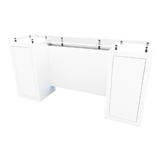
Order #XXXXX - ECO-42C Sustainable Counter / Podium
Item
Qty.
Description
17/17A
1/1
46"w CEI110 Horizontal Extrusion
18/18A
1/1
30.5"h CEI110 Vertical Extrusion
Steps:
1) Connect horizontals [17,17A] between
verticals [18,18A], sliding backer panel between
verticals. See
CEI-110 Corner Connection
2) Attach left & right cabinets to frame
assembly [17/17A/18/18A] using bolts & wing nuts.
3) Install
Counter Top
to assembly using standoff
barrels as shown.
See
Standoff Barrel Attachment
detail.
4) Connect power cords to Supernova lights as shown.
5) Apply SEG graphic to frame.
*
18
TOP VIEW
CEI110
bolt &
*
Backer
wing nut
Lights
FRONT
SEG Graphic Installation
Corner A
Corner B
Corner D
Corner C
It is important to first insert
Step 1
Step 2
graphic into each alternate
Insert corner A. Turn edge of
Repeat Step 1 for opposite
corner then to the sides of
graphic so silicon welt is
corner C, then insert corner
the frame. If this is not done,
perpendicular to face of
B, followed by corner D, to
graphic will not fit into the
graphic. Insert narrow side
complete the installation of
frame correctly.
of welt with fabric to outside
the corners.
into the channel. Repeat for
other side of this corner.
866.463.2611 • www.ecosystemsdisplays.com
*
CEI-110 Corner Connection
TSRV2
A1
Bracket
1) Insert TSRV2 and A1 Brackets
into milled groove of extrusion.
2) Slide connecting extrusion over
exposed end of brackets.
detail.
3) Use Set screws to secure
extrusions.
4) Use Set screws to secure
extrusions.
17A
*
B a c k e r
P a n e l
18A
*
17
Graphic Removal
Step 3
Once all corners are inserted,
To remove the graphic
from
press one silicon edge into
the frame, locate the fabric
channel from corners and
pull tab. Gently pull up on the
work
toward
the
center.
tab to remove the fabric.
Make sure welt is fully inserted
into channel. Continue until
all sides are done. Smooth
out edges of graphic.
*
Standoff Barrel Attachment
Slide V4 connector into
horizontal groove of
extrusion; tighten set
set
screw
screw to secure.
V4
Connect Standoff Barrel to V4.
standoff
caps
1.5" standoff
barrels
To
Power
Light to Light Attachment
Transformer
Male
+
+
Lights
-
-
Light to Tranformer Attachment
+
-
Female
Power
Transformer
Maximum of 7 lights per chain,
9 lights per Transformer
standoff
barrel
When assembled
standoff
caps
Counter Top
4.5" standoff
Note:
barrels
No standoff
cap for
*
middle
*
barrel.
*
hole for wire
management
1.5" standoff
barrels
Advertisement
Table of Contents

Related Manuals for Eco-Systems ECO-42C


Summary of Contents for Eco-Systems ECO-42C
- Page 1 Order #XXXXX - ECO-42C Sustainable Counter / Podium Item Qty. Description CEI-110 Corner Connection 17/17A 46”w CEI110 Horizontal Extrusion TSRV2 Standoff Barrel Attachment 18/18A 30.5”h CEI110 Vertical Extrusion Bracket 1) Insert TSRV2 and A1 Brackets Steps: standoff Slide V4 connector into barrel into milled groove of extrusion.
- Page 2 General Setup Instructions •The setup instructions are created specifically for your configuration. •Setup instructions are laid out sequentially in levels, including exploded views and a logical series of steps for assembly. We encourage you to study the instructions before attempting to assemble your exhibit. Cleaning and Packing •Use non-abrasive cleaners when cleaning extrusions or ECO Glass inserts.
Need help?
Do you have a question about the ECO-42C and is the answer not in the manual?
Questions and answers