Table of Contents
Advertisement
Quick Links
I
, O
& M
M
NSTALLATION
PERATION
AINTENANCE
ANUAL
Versymmetric
Two Post
TM
Surface Mounted Lift
M
OE-9
ODEL
9,000
. C
LBS
APACITY
2250
.
A
LBS
PER
RM
200 Cabel Street, P.O. Box 3944 Louisville, Kentucky 40201-3944
Email:
Web site:
sales@challengerlifts.com
www.challengerlifts.com
/
Office 800-648-5438
502-625-0700 Fax 502-587-1933
IMPORTANT:
READ THIS MANUAL COMPLETELY BEFORE
INSTALLING or OPERATING LIFT
Rev. 02/12/08
Advertisement
Table of Contents

Related Manuals for Challenger Lifts Magnum Versymmetric OE-9


Summary of Contents for Challenger Lifts Magnum Versymmetric OE-9
- Page 1 & M NSTALLATION PERATION AINTENANCE ANUAL Versymmetric Two Post Surface Mounted Lift OE-9 ODEL 9,000 APACITY 2250 200 Cabel Street, P.O. Box 3944 Louisville, Kentucky 40201-3944 Email: Web site: sales@challengerlifts.com www.challengerlifts.com Office 800-648-5438 502-625-0700 Fax 502-587-1933 IMPORTANT: READ THIS MANUAL COMPLETELY BEFORE INSTALLING or OPERATING LIFT Rev.
-
Page 2: Specifications
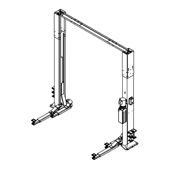
Model OE-9 Installation, Operation and Maintenance ENERAL PECIFICATIONS See Figure 1 OE-9 OE-9-1 OE-9-2 11’-8” or 11’-2” 12’-8” or 12’-2” 13’-8” or 13’-2” Adjustable Column Height 11’-2” or 10’-8” 12’-2” or 11’-8” 13’-2” or 12’-8” Floor to Overhead Switch 74 5/8” Rise Height (Screw Pads Highest Position) 11’-11”... - Page 3 Model OE-9 Installation, Operation and Maintenance Safety decals similar to those shown here are ERTICAL LEARANCE found on a properly installed lift. Be sure that all Check the height of the area where the lift is to safety decals have been correctly installed on the be installed.
- Page 4 Standard open end wrenches 7/16”, 1/2", the shorted or damaged goods. Do this for your (2) 9/16”, (2) 11/16”, 3/4" own protection. g. 5/16” allen wrench Challenger Lifts NOTIFY AT ONCE if any h. Needle nose pliers hidden loss or damage is discovered after Hammer drill with 3/4”...
- Page 5 Model OE-9 Installation, Operation and Maintenance 8) Shim both columns to plumb using the shims 13) Install Overhead Limit Switch to Power provided as shown in Fig 2. DO NOT shim Column using (1) 3/8” pivot pin, (1) 3/8” flat more than 1/2"...
- Page 6 Model OE-9 Installation, Operation and Maintenance 15) Assemble the sheaves, spacers and washers cable. Fig 8. Route synchronizing cables onto the sheave pin as shown in Fig 5. Set in using Fig 7a and attach ends to cable-tie-off cradle with all assembly parts between the tabs using Fig’s 7b &...
- Page 7 Model OE-9 Installation, Operation and Maintenance 20) Once cables are routed install the lower 23) Tighten the thin Jam Nuts against the Cable cable trap devices sliding along the inside Adjustment Nut. edge of the column and under the sheave. &...
- Page 8 Model OE-9 Installation, Operation and Maintenance Thread opposite end of hose into male #6 HYDRAULIC HOSE CLAMP HYDRAULIC HOSE CLAMP HYDRAULIC HOSE CLAMP HYDRAULIC HOSE CLAMP WITH 3/8"-16 HEX FLANGE WITH 3/8"-16 HEX FLANGE WITH 3/8"-16 HEX FLANGE WITH 3/8"-16 HEX FLANGE SNAKE EXCESS HOSE SNAKE EXCESS HOSE SNAKE EXCESS HOSE...
- Page 9 Model OE-9 Installation, Operation and Maintenance Fig 12 – Power Column Lock Assembly 33) Route opposite end of cable assembly up left side of Power Column and into column Fig 13 – Idler Column Lock Assembly through access slot (3/8”x4” Lg.) in bottom of 35) Insert threaded sleeve portion of cable Column Extension.
- Page 10 Model OE-9 Installation, Operation and Maintenance INAL DJUSTMENTS YDRAULICS 41) Lower the lift to the floor and raise the lift approximately one foot. 42) Start with Idler side first. Slowly and carefully loosen the bleed plug on top of the cylinder just enough to allow the entrapped air to escape.
-
Page 11: Wiring Diagram
Model OE-9 Installation, Operation and Maintenance Wiring Diagram FOR SINGLE PHASE (Normally Open) FIELD CONECTIONS FOR THREE PHASE FACTORY WIRED FOR 208−240V RECONNECTIONS FOR 440−480V Fig 14 – Electrical Wiring Diagram Page 11 Rev. 02/1208 A1151_MAGNUM.doc... -
Page 12: Operation Procedure
Owner/Employer shall establish questionnaires to: procedures to periodically maintain the lift in Challenger Lifts, Inc. accordance with lift manufacturer’s instructions or ANSI/ALIOIM-2000, American 200 Cabel Street National Standard for Automotive Lifts-Safety Louisville, KY. - Page 13 Replace as required with genuine above the desired working height. Challenger Lifts parts. 5) Lower the vehicle until the safety latches on • Check lock release cable adjustment per both columns engage.
-
Page 14: Parts Breakdown
Replace all worn or broken parts with genuine Challenger Lifts Inc. parts. Contact your local Challenger Lifts Parts Distributor for pricing and availability. (Call Challenger Lifts Inc. (502) 625-0700 for the Parts Distributor in your area) Page 14 Rev. 02/1208... -
Page 15: Fig B. Lock
Replace all worn or broken parts with genuine Challenger Lifts Inc. parts. Contact your local Challenger Lifts Parts Distributor for pricing and availability. (Call Challenger Lifts Inc. (502) 625-0700 for the Parts Distributor in your area) Page 15 Rev. 02/1208... -
Page 16: Fig C. Hydraulics
Replace all worn or broken parts with genuine Challenger Lifts Inc. parts. Contact your local Challenger Lifts Parts Distributor for pricing and availability. (Call Challenger Lifts Inc. (502) 625-0700 for the Parts Distributor in your area) Page 16 Rev. 02/1208... -
Page 17: Fig D. Synchronizer
Replace all worn or broken parts with genuine Challenger Lifts Inc. parts. Contact your local Challenger Lifts Parts Distributor for pricing and availability. (Call Challenger Lifts Inc. (502) 625-0700 for the Parts Distributor in your area) Page 17 Rev. 02/1208... - Page 18 Replace all worn or broken parts with genuine Challenger Lifts Inc. parts. Contact your local Challenger Lifts Parts Distributor for pricing and availability. (Call Challenger Lifts Inc. (502) 625-0700 for the Parts Distributor in your area) Page 18 Rev. 02/1208...
- Page 19 Replace all worn or broken parts with genuine Challenger Lifts Inc. parts. Contact your local Challenger Lifts Parts Distributor for pricing and availability. (Call Challenger Lifts Inc. (502) 625-0700 for the Parts Distributor in your area) Page 19 Rev. 02/1208...
- Page 20 Model OE-9 Installation, Operation and Maintenance BLANK PAGE Page 20 Rev. 02/1208 A1151_MAGNUM.doc...