Table of Contents
Advertisement
Advertisement
Table of Contents

Related Manuals for Challenger Lifts 12000


Summary of Contents for Challenger Lifts 12000
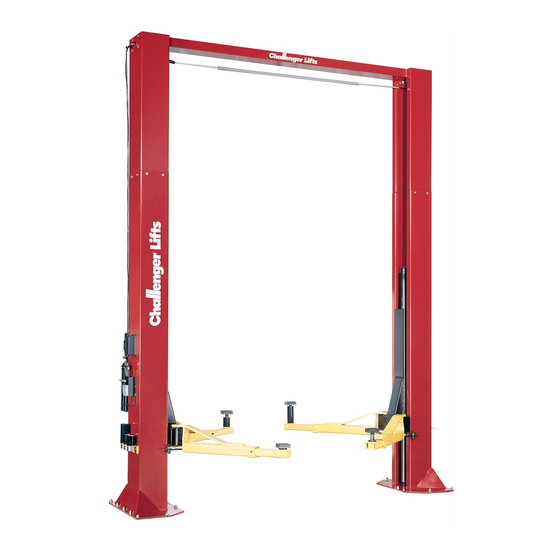
- Page 1 Challenger Lifts, Inc. MODEL 12000 TWO POST SURFACE MOUNTED LIFT OPERATION, INSTALLATION & MAINTENANCE MANUAL IMPORTANT READ THIS MANUAL COMPLETELY BEFORE INSTALLING OR OPERATING THE LIFT 200 CABEL STREET, P.O. BOX 3944 LOUISVILLE, KENTUCKY 40201-3944 OFFICE (502) 625-0700 FAX (502) 587-1933...
- Page 2 Model 12000 Installation, Operation and Maintenance General Specifications Maximum Capacity*........12000 US Pounds (3000 Pounds Per Arm) Lifting Time**................Approximately 1 Minute Lowering Time** ..............Approximately 45 Seconds Motor ............... 2HP, 230 Volts, Single Phase, 60 Hz. Optional-2HP, 208 or 240 or 480 Volt, 3 Phase, 50/60 Hz.
- Page 3 Challenger Lifts, Inc. Immediately. 2. Be certain that the wiring in your building will handle the current required to operate this unit (Fig 9).
- Page 4 Model 12000 Installation, Operation and Maintenance Installation Procedure 1. Break down the packaging with the columns by supporting the upper column and using a 3/4" wrench, remove the bolts at the top and bottom of the column. Carefully remove the top cap.
- Page 5 Model 12000 Installation, Operation and Maintenance 3. Assemble a column extension to each column using 3/8 x 1 bolts, flat washers, lock washers, and nuts. 4. Erect both column assemblies. Align the columns with the installation lines and drill the holes for the anchors using the base plate as a template.
- Page 6 Model 12000 Installation, Operation and Maintenance 9. Take the shutoff bar to the idler column side and first insert the end of the bar into the open end of the switch tube, then attach the other end to the bracket on the idler side of the overhead using the 3/8 x 1 shoulder bolt, 5/16 dia.
- Page 7 Model 12000 Installation, Operation and Maintenance 11. Manually raise the carriages to a comfortable working height and set in locks at equal heights. Route the synchronizer cables (Fig. 5). For Models 12001 & 12002 (extended height models) cable extensions are required. Install one extension inside each carriage for both models and an additional extension on top of each carriage for Model 12002.
- Page 8 Model 12000 Installation, Operation and Maintenance 13. Connect the extension hydraulic lines to the cylinder lines in each column using a straight union on the idler side and a tee on the power side. Install the overhead line with the longer leg on the idler side.
- Page 9 Model 12000 Installation, Operation and Maintenance 15. Route the 1/8" air line (Fig. 8). Be certain not to kink or pinch the hose. Connect the button valve to a source of clean, dry air using the hose barb and clamp provided. Snap the covers onto the column.
- Page 10 Model 12000 Installation, Operation and Maintenance 17. Connect the overhead shutoff switch to the power unit (Fig. 9). 18. Connect the power unit to a suitable electrical power (Fig. 9). Wiring Diagram Wiring Diagram Wiring Diagram Wiring Diagram FOR SINGLE PHASE...
- Page 11 Model 12000 Installation, Operation and Maintenance 19. Energize the power unit until the carriages are lifted and run them up about 3 feet. Caution! Wear eye protection while bleeding the cylinders! Slowly and carefully loosen the bleed plug to allow the entrapped air to escape from the cylinder, first on the idler side and then the power side.
- Page 12 Installation, Operation and Maintenance Operation Procedure Notice: This Challenger 12000 Surface Mounted lift has been designed and constructed according to ANSI/ALI ALCTV-1998 standard to insure that it is safe to use. The standard applies to lift manufactures, as well as to owners and employers. The owner/employer=s responsibilities, as prescribed by ANSI/ALI ALCTV-1998, are summarized below.
- Page 13 Model 12000 Installation, Operation and Maintenance Lifting a Vehicle Ensure that the lifting arms are parked, out of the way of the vehicle. Position the vehicle in the service bay so that the vehicle=s center of gravity is on a line between the two columns, and so the vehicle is centered between the two columns.
- Page 14 Model 12000 Installation, Operation and Maintenance Lowering a vehicle Ensure that the area under the vehicle is clear of personnel and tools. Raise the vehicle until both latches are free. Disengage the latches by depressing the palm button and holding it.
- Page 15 Model 12000 Installation, Operation and Maintenance Appendix A Hydraulic Fitting Assembly Hydraulic line sets are prefabricated to allow easy assembly in the field. Follow the steps outlined below for reliable, leak-free joint: Remove any shipping plugs or caps, insuring that no remnants of the plugs or caps remain in the tube.
- Page 16 Model 12000 Installation, Operation and Maintenance Appendix B Anchor Bolt Installation Insure the concrete has had sufficient time to cure - 28 days minimum. Always wear safety glasses. Follow the drill manufacturers safety instruction. Use only solid carbide-tipped drill bits meeting ANSI B94 tip diameter standards.
- Page 17 Model 12000 Installation, Operation and Maintenance P/N 12580 Rev. 12/99...
- Page 18 POWER UNIT - THREE PHASE Replace worn or broken parts with genuine CHALLENGER LIFTS INC. parts Contact your local Challenger Lifts Parts Distributor for pricing and availability (Call CHALLENGER LIFTS INC. (502) 625-0700 for the Parts Distributor in your area) P/N 12580 Rev. 12/99...
Need help?
Do you have a question about the 12000 and is the answer not in the manual?
Questions and answers