Table of Contents
Advertisement
Quick Links
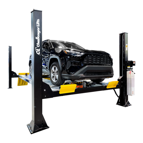
Installation, Operation & Maintenance Manual
Four Post
Surface Mounted Lift
Models Q4P09H, Q4P09X & Q4P09W
(9,000 lb. Capacity)
2311 South Park Rd Louisville, Kentucky 40219
Email:sales@challengerlifts.com
Web
site:www.challengerlifts.com
Office 877-771-5438/ 502-583-5438 Fax 502-583-5488
IMPORTANT:
READ THIS MANUAL COMPLETELY BEFORE
INSTALLING or OPERATING LIFT
Rev 2024/03/25
Advertisement
Table of Contents

Related Manuals for Challenger Lifts Quality Lifts Q4P09W


Summary of Contents for Challenger Lifts Quality Lifts Q4P09W
- Page 1 Installation, Operation & Maintenance Manual Four Post Surface Mounted Lift Models Q4P09H, Q4P09X & Q4P09W (9,000 lb. Capacity) 2311 South Park Rd Louisville, Kentucky 40219 Email:sales@challengerlifts.com site:www.challengerlifts.com Office 877-771-5438/ 502-583-5438 Fax 502-583-5488 IMPORTANT: READ THIS MANUAL COMPLETELY BEFORE INSTALLING or OPERATING LIFT Rev 2024/03/25...
- Page 2 Models Q4P09H, Q4P09X & Q4P09W Installation, Operation and Maintenance ENERAL PECIFICATIONS Q4P09H Q4P09X Q4P09W SPECIFICATIONS 209½” [17’-5½”] 233½” [19’-5½”] 233 ½” [19’-5½”] Length Overall 112¼” 112¼” 127¼” Width Overall 95” 95” 110” Inside Columns 160½” [13’-4½”] 184¾” [15’-4¾”] 184¾” [15’-4¾”] Between Columns 84½”...
- Page 3 Models Q4P09H, Q4P09X & Q4P09W Installation, Operation and Maintenance Fig 2 – Drive Under Height Q4P09-IOM-Q.doc Rev 2024/03/25...
-
Page 4: Vertical Clearance
Models Q4P09H, Q4P09X & Q4P09W Installation, Operation and Maintenance ERTICAL LEARANCE AFETY OTICES AND ECALS Check the height of the area where the lift is to be For your safety, and the safety of others, read and installed. Clearance should be calculated based on understand all of the safety notices and decals the full raised height of the lift. -
Page 5: Installation
Models Q4P09H, Q4P09X & Q4P09W Installation, Operation and Maintenance Receiving Component Packing List The shipment should be thoroughly inspected as ITEM QTY/ soon as it is received. The signed bill of lading is DESCRIPTION LIFT acknowledgement by the carrier of receipt in good IDLER RUNWAY ASS’Y condition of shipment covered by our invoice. - Page 6 Models Q4P09H, Q4P09X & Q4P09W Installation, Operation and Maintenance 3) Remove the mechanical lock release bar from the Idler Runway. 4) Check the lock release bar to ensure it is secure and that the lock pawl is in the correct position as shown in Fig 4.
- Page 7 Models Q4P09H, Q4P09X & Q4P09W Installation, Operation and Maintenance 11) Position the front and rear cross beams, Fig 7. Fig 10 – Cable Layout Fig 8 – Hydraulic Ports 12) Remove the four (4) cross beam sheaves (one sheave from each end). The runway sheave pins do not need to be removed.
- Page 8 Models Q4P09H, Q4P09X & Q4P09W Installation, Operation and Maintenance 20) Check the layout of the lift in the bay. anchoring the lift, this is the last chance to make adjustments. Adjust the position of the runways so the distance from power side jack rail to idler side jack rail is the same at the front and the rear and the diagonal measurements from the front tip of one rail to rear tip of the...
-
Page 9: Power Unit
Models Q4P09H, Q4P09X & Q4P09W Installation, Operation and Maintenance NOTE: Level bubble should not only be between the lines, the bubble should be centered between the lines. If shims do not allow sufficient centering of the bubble, it is best to lean the rear columns in the direction toward each other and the front columns in the direction toward each other. -
Page 10: Owner /Operator Checklist
Models Q4P09H, Q4P09X & Q4P09W Installation, Operation and Maintenance NOTE: When attaching the return line to the OLUMN ECAL LACEMENT bulk head in the runway, make sure it is 46) Center the decal on the front drivers side securely attached at the power unit, and the column and rear passenger side column. -
Page 11: Operation Procedure
Models Q4P09H, Q4P09X & Q4P09W Installation, Operation and Maintenance Fig 24 – NON STANDARD 230V WIRING DIAGRAM Operation, Inspection and Maintenance; and the PERATION ROCEDURE employer shall ensure that the lift maintenance personnel are qualified and that they are AFETY OTICES AND ECALS adequately trained in the maintenance of the lift. - Page 12 Models Q4P09H, Q4P09X & Q4P09W Installation, Operation and Maintenance IFTING A EHICLE AINTENANCE Place entrance ramps in the slotted holes on the To avoid personal injury, permit only qualified front of the ramp. Drive vehicle onto lift. Set the personnel to perform maintenance on this parking brake.
- Page 13 Models Q4P09H, Q4P09X & Q4P09W Installation, Operation and Maintenance (Q4P09DT) (Q4P09CS) OBILITY 1) Place drip tray between runways in the Jack rail, 1) This set of four casters when attached to the Fig 26. cross beams of an unloaded lift, Fig 29, pick the lift up and allow it to be rolled to a different 2) Slide along jack rail until its in desired location.
- Page 14 Models Q4P09H, Q4P09X & Q4P09W Installation, Operation and Maintenance (Q4P09PR OPTIONAL) IVOTING 1) Raise the lift to a comfortable working height 6) Assemble the ramp to the base with the ramp and set into the locks. hinge pin. Use the provided cotter pins to secure the pin in place, Fig 33.
-
Page 15: Parts Breakdown
Models Q4P09H, Q4P09X & Q4P09W Installation, Operation and Maintenance Parts Breakdown Models Q4P09H, Q4P09X & Q4P09W IMPORTANT!!! Replace all worn or broken parts with genuine Quality Lifts Inc. parts. Contact your local Quality Lifts Parts Distributor for pricing and availability. (Call Quality Lifts Inc. - Page 16 Models Q4P09H, Q4P09X & Q4P09W Installation, Operation and Maintenance Parts Breakdown Fig A. General Layout Q4P09-IOM-Q.doc Rev 2024/03/25...
- Page 17 Models Q4P09H, Q4P09X & Q4P09W Installation, Operation and Maintenance ITEM # PART # QTY/LIFT DESCRIPTION TCS4-08-01-00A (Q4P09H) IDLER RUNWAY WELD TCS4A-08-01-00 (Q4P09X & W) TCS4-07-01-00A (Q4P09H) POWER RUNWAY WELD TCS4A-07-01-00 (Q4P09X & W) TCS4-01-00-xx (Q4P09H) POWER COLUMN ASSY -xx = COLOR CODE TCS4A-01-00-xx (Q4P09X &...
- Page 18 Models Q4P09H, Q4P09X & Q4P09W Installation, Operation and Maintenance PARTS BREAKDOWN (continued) Fig B. Cables ITEM # PART # QTY/LIFT DESCRIPTION TCS4-11-02 (174 7/8”) (Q4P09 H) PASSENGER SIDE REAR CABLE TCS4A-11-02 (187”) (Q4P09 X) Cable #2 TCS4B-11-02 (194 ½”) (Q4P09 W) TCS4-11-04 (353 5/8”) (Q4P09 H) PASSENGER SIDE FRONT...
- Page 19 Models Q4P09H, Q4P09X & Q4P09W Installation, Operation and Maintenance PARTS BREAKDOWN (continued) Fig C. Runway Sheaves ITEM # PART # QTY/LIFT DESCRIPTION 40053 1/8” THICK BEARING TCS4-04-03-00 SHEAVE ASSEMBLY TCS4-07-04-00 SHEAVE PIN ASSEMBLY (RUNWAY) B31188 M8 x 16mm Lg. HEX LOCKING FLG. HD. CAP SCREW TCS4-07-03 RUNWAY SHEAVE SPACER –...
- Page 20 Models Q4P09H, Q4P09X & Q4P09W Installation, Operation and Maintenance PARTS BREAKDOWN (continued) Fig D. Cross Beams Q4P09-IOM-Q.doc Rev 2024/03/25...
- Page 21 Models Q4P09H, Q4P09X & Q4P09W Installation, Operation and Maintenance ITEM # PART # QTY/LIFT DESCRIPTION TCS4-04-01-00A FRONT CROSSBEAM WELD (Q4P09H & X) TCS4B-04-01-00 FRONT CROSSBEAM WELD (Q4P09W) TCS4-05-01-00A REAR CROSSBEAM WELD (Q4P09H & X) TCS4B-05-01-00 REAR CROSSBEAM WELD (Q4P09W) TCS4-04-02 SLIDE BLOCK B40127 LOCK PIVOT PIN...
-
Page 22: Caster Assembly
Models Q4P09H, Q4P09X & Q4P09W Installation, Operation and Maintenance Caster Assembly ITEM # PART # QTY/ASSY DESCRIPTION TCS4-06-01-00A Caster Weldment TCS4-06-03 Caster Wheel X10-077 Bolt, M10 x 25mm Long X10-019 Nut, M10 X10-073 Washer, 10mm TCS4-06-02 Pivot Pin GJY12-3 Hairpin cotter A1075 Pull Ring Q4P09-IOM-Q.doc... - Page 23 Models Q4P09H, Q4P09X & Q4P09W Installation, Operation and Maintenance REVISIONS 2020/08/10 – UPDATED THE 115V POWER UNIT PART NUMBER. 2020/10/05 – UPDATED MECHANICAL LOCK COUPLER AND ENTRANCE RAMP PART NUMBER IN THE PARTS BREAKDOWN. 2020/12/15 – CHANGED POWER UNIT FORM 31368-19 TO AB-9367/DLH. UPDATED WIRING DIAGRAM AND PARTS BREAKDOWN.
Need help?
Do you have a question about the Quality Lifts Q4P09W and is the answer not in the manual?
Questions and answers