Table of Contents
Advertisement
I
NSTALLATION
200 Cabel Street, P.O. Box 3944 Louisville, Kentucky 40201-3944
Email:
Office 800-648-5438
IMPORTANT:
, O
PERATION
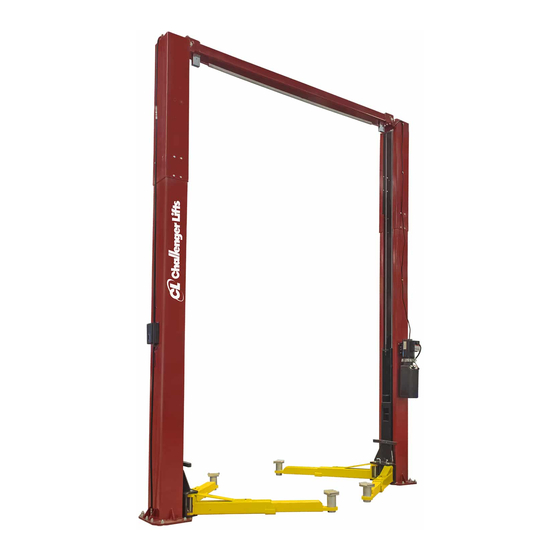
Two Post
Surface Mounted Lift
M
ODEL
12,000
LBS
3000
LBS
sales@challengerlifts.com
/
502-625-0700 Fax 502-587-1933
READ THIS MANUAL COMPLETELY BEFORE
INSTALLING or OPERATING LIFT
& M
AINTENANCE
E12
. C
APACITY
.
A
PER
RM
Web site:
www.challengerlifts.com
M
ANUAL
Rev. 11/29/16
Advertisement
Table of Contents

Related Manuals for Challenger Lifts E12


Summary of Contents for Challenger Lifts E12
- Page 1 & M NSTALLATION PERATION AINTENANCE ANUAL Two Post Surface Mounted Lift ODEL 12,000 APACITY 3000 200 Cabel Street, P.O. Box 3944 Louisville, Kentucky 40201-3944 Email: Web site: sales@challengerlifts.com www.challengerlifts.com Office 800-648-5438 502-625-0700 Fax 502-587-1933 IMPORTANT: READ THIS MANUAL COMPLETELY BEFORE INSTALLING or OPERATING LIFT Rev.
-
Page 2: Specifications
Model E12 Installation, Operation and Maintenance ENERAL PECIFICATIONS See Figure 1 E12 w/ 2 Ft. Ext. Kit 77 3/4" Rise Height (Screw Pads Highest Position) (1975 mm) 13’-10"/14’-7” 15’-10"/16’-7” Overall Height (4216 mm/4445 mm) (4826mm/ 5055mm) 139 3/4" Overall Width (3550 mm) 103"... -
Page 3: Vertical Clearance
Model E12 Installation, Operation and Maintenance ERTICAL LEARANCE Safety decals similar to those shown here are found on a properly installed lift. Be sure that all Check the height of the area where the lift is to safety decals have been correctly installed on the be installed. -
Page 4: Installation
Model E12 Installation, Operation and Maintenance ECEIVING NSTALLATION The shipment should be thoroughly inspected as MPORTANT Always wear safety glasses while installing lift. soon as it is received. The signed bill of lading is OOLS MINIMUM REQUIRED acknowledgement by the carrier of receipt in a. - Page 5 Model E12 Installation, Operation and Maintenance NCHORING 4) The anchor bolts must be installed at least 8” from any crack, edge, or expansion joint. 5) Use a concrete hammer drill with a 3/4 inch carbide bit. Tip diameter should conform to ANSI Standard B94.12-1977 (.775 to .787).
- Page 6 Model E12 Installation, Operation and Maintenance 18) Repeat for opposite side. Fig 7 – Hyd. Tee Fitting 22) IMPORTANT – To insure proper hose fitting seal without damage to the fitting follow this procedure for each hose connection: Screw flared fitting on finger tight.
-
Page 7: Lock Release
Model E12 Installation, Operation and Maintenance ELEASE IMPORTANT: FTER WIRING BEEN & COMPLETED TEST OPERATION OF OWER 27) Install Lock Release Stud and Knob to the VERHEAD IMIT SWITCH HILE RAISING LIFT Powre Column Lock using one M10 Nut. OPERATE... - Page 8 Model E12 Installation, Operation and Maintenance wiped clean from the cylinder rod, the cylinder will apear to be leaking. YNCHRONIZING ABLES 45) Raise lift and insure carriages lower into same lock position. 46) Adjust synchronizing cables so the tension is equal in both cables and carriages are firmly sitting on locks.
- Page 9 Model E12 Installation, Operation and Maintenance Wiring Diagram FOR SINGLE PHASE FIELD CONECTIONS (Normally Open) FIELD CONECTIONS FOR THREE PHASE FACTORY WIRED FOR 208−240V RECONNECTIONS FOR 440−480V Fig 10 – Electrical Wiring Diagram Page 9 Rev. 11/29/16 E12-IOM-A.
-
Page 10: Operation Procedure
Model E12 Installation, Operation and Maintenance 90 ALI Safety Tips card; ANSI/ALI ALOIM-2008, PERATION ROCEDURE American National Standard for Automotive Lifts- AFETY OTICES AND ECALS Safety Requirements for Operation, Inspection and Maintenance; and in the case of frame This product is furnished with graphic safety... -
Page 11: Lifting A Vehicle
Model E12 Installation, Operation and Maintenance IFTING A EHICLE OWERING EHICLE 1) Insure that the lifting arms are parked, out to 1) Insure that the area under the vehicle is clear full drive thru position. of personnel and tools. 2) Position the vehicle in the service bay so that 2) Raise the vehicle until both locks are free. -
Page 12: Maintenance
Model E12 Installation, Operation and Maintenance AINTENANCE To avoid personal injury, permit only qualified personnel to perform maintenance on this equipment. Maintenance personnel should follow lockout/tagout instructions per ANSI Z244.1. The following maintenance points are suggested as the basis of a routine maintenance program. -
Page 13: Parts Breakdown
M12 LOCK WASHER X10-040 M12 NUT Replace all worn, damaged, or broken parts with parts approved by Challenger Lifts Inc. or with parts meeting Challenger Lifts Inc. specifications. Contact your local Challenger Lifts Parts Distributor for pricing and availability. (Call Challenger Lifts Inc. (502) 625-0700 for the Parts Distributor in your area) Page 13 Rev. - Page 14 JSJ6-06H LOCK RELEASE CABLE ASSEMBLY (2Ft. Ext. Height) Replace all worn, damaged, or broken parts with parts approved by Challenger Lifts Inc. or with parts meeting Challenger Lifts Inc. specifications. Contact your local Challenger Lifts Parts Distributor for pricing and availability.
- Page 15 O-RING x 9/16-18 UN 90 DEGREE ELBOW 31368-19 POWER UNIT Replace all worn, damaged, or broken parts with parts approved by Challenger Lifts Inc. or with parts meeting Challenger Lifts Inc. specifications. Contact your local Challenger Lifts Parts Distributor for pricing and availability.
- Page 16 M12 LOCK WASHER X10-053 M12 x 45mm BOLT Replace all worn, damaged, or broken parts with parts approved by Challenger Lifts Inc. or with parts meeting Challenger Lifts Inc. specifications. Contact your local Challenger Lifts Parts Distributor for pricing and availability.
- Page 17 JSJ5-23CH M8 x 8 Set Screw Cup Point Replace all worn, damaged, or broken parts with parts approved by Challenger Lifts Inc. or with parts meeting Challenger Lifts Inc. specifications. Contact your local Challenger Lifts Parts Distributor for pricing and availability.
Need help?
Do you have a question about the E12 and is the answer not in the manual?
Questions and answers