Table of Contents
Advertisement
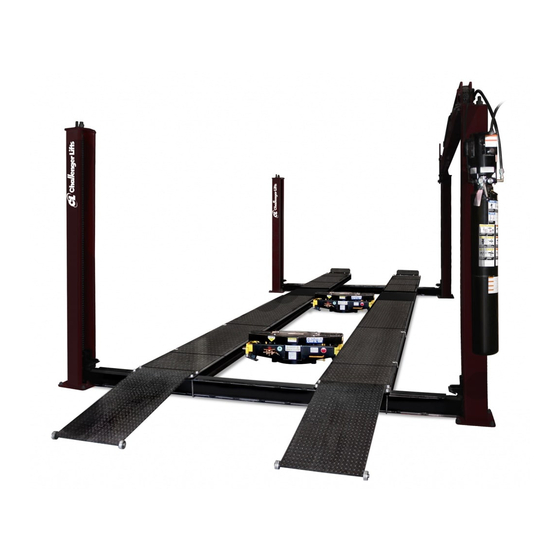
Installation, Operation & Maintenance Manual
M
D
EDIUM
UTY
F
P
L
OUR
OST
IFT
18,000 lbs Capacity
Model 44018
Model 44018E
2311 South Park Rd Louisville, Kentucky 40219
sales@challengerlifts.com
www.challengerlifts.com
Email:
Web site:
Office 800-648-5438 / 502-625-0700 Fax 502-587-1933
READ THIS MANUAL COMPLETELY
IMPORTANT:
BEFORE INSTALLING or OPERATING LIFT
Rev. 05/22/2017
Advertisement
Table of Contents

Related Manuals for Challenger Lifts 44018


Summary of Contents for Challenger Lifts 44018
- Page 1 Installation, Operation & Maintenance Manual EDIUM 18,000 lbs Capacity Model 44018 Model 44018E 2311 South Park Rd Louisville, Kentucky 40219 sales@challengerlifts.com www.challengerlifts.com Email: Web site: Office 800-648-5438 / 502-625-0700 Fax 502-587-1933 READ THIS MANUAL COMPLETELY IMPORTANT: BEFORE INSTALLING or OPERATING LIFT...
- Page 2 Rev. 05/22/2017...
-
Page 3: Cautions And Warnings
2. Read the installation manual before installing the lift. 3. This lift is a four post lift which requires a minimum (44018) 14’ x 25’-6” (44018E.) 14’ x 28’-6” bay area. 4. Read anchoring tips information before drilling and installing the anchor bolts. -
Page 4: Tools Required
Place a flat washer over threaded end of anchor. Spin nut 1 /2” down past end of anchor. Carefully tap anchor into the concrete until nut and flat washer are against base plate. Do not use an impact wrench to tighten. Rev. 5/22/2017 44018-IOM-A.doc... -
Page 5: Installation Instructions
1/2” flat washers left fro m packing for shims. Keep shims as close to a nchors as possible. Now you may tighten the anchor bolts on first leg only. Do not use an necessary. impact wrench. Re-check for plumb and adjust if Rev. 5/22/2017 44018-IOM-A.doc... - Page 6 Attach loose end of chain to each cross rail connector using 5/16 x 3 1/2” Grade 8 bolt and nuts. Do not substitute this bolt!!!! Repeat on other cross rail. Replace fitting on cylinder. Rev. 5/22/2017 44018-IOM-A.doc...
- Page 7 34. Position and install stops on opposite end of vehicle approach end. Drop ramps on slotted hole of the approach end. 35. Cycle the lift it it’s maximum height and back to the ground at least 3 full cycles without any load to remove air from the hydraulic system. Rev. 5/22/2017 44018-IOM-A.doc...
- Page 8 Lifting It Right booklet as a guide. Complete the Installation Checklist/Warranty Validation que stionnaire with th e owner. Review the terms of the warranty registration card, and return the card and a copy of the questionnaires Challenger Lifts, Inc. 200 Cabel Street Louisville, KY. 40206...
-
Page 9: Lifting A Vehicle
Check hydraulic system for fluid leaks. Check lock release activation. Weekly Check chains and sheaves for wear or damage. Replace as required with genuine Challenger Lifts parts. Inspect lock mechanism for proper function. Monthly Torque concrete anchor bolts to 80 ft-lbs. -
Page 10: Lock Washer
CUHC10500ZTAP727E 12087-19 Power Unit ALGF-412-034 Ramp Pivot Pin ALIF-412-001-XX Front Stop ALIF-418-016-XX Weldm’t. 2 PKG ALIF-418-012-XX 44018 Track Weldm’t. ALIF-418-212-XX 44018E Track Weldm’t. 2 PKG ALIG-415-049 Offside Leg Chain Connector 2 PKG ALIF-418-011 Sq. U-Bolts ALIF-418-022L-XX Mainside Leg Weldm’t. 1 PKG ALIF-418-022R-XX Mainside Leg Weldm’t. - Page 11 1 Dia. Cylinder Pin ALIG-418-111 1 3/8 Dia. Pulley Pin ALIG-418-113 BL844, 99 Pitch, Short Top Rail Chain ALIG-418-114 (44018) BL844, 291 Pitch, Long Top Rail Chain ALIG-418-214 (44018E) BL844, 327 Pitch, Long Top Rail Chain GL-12-053-XX 5.5 Dia. Top Rail Wheel GL-12-056 Dia.
Need help?
Do you have a question about the 44018 and is the answer not in the manual?
Questions and answers