Challenger Lifts Versymmetric CL10 Installation, Operation & Maintenance Manual
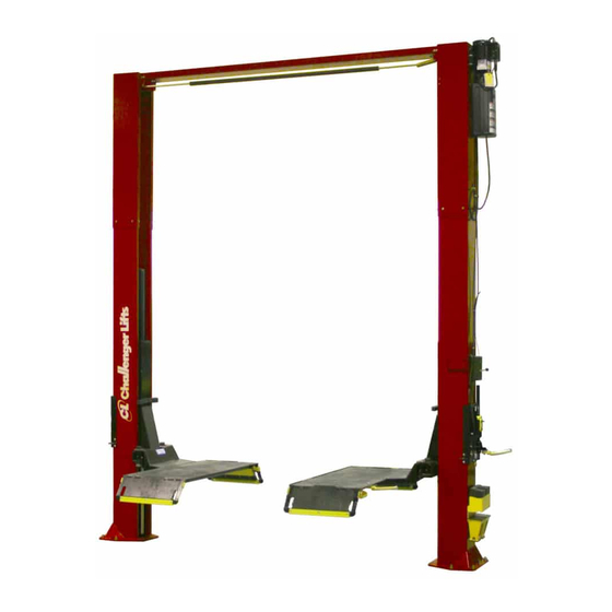
Two post surface mounted lift
Hide thumbs
Also See for Versymmetric CL10:
- Installation, operation & maintenance manual (24 pages) ,
- Installation & operation manual supplement (7 pages) ,
- Installation, operation & maintenance manual (23 pages)
Table of Contents
Advertisement
Quick Links
V
200 Cabel Street, P.O. Box 3944 Louisville, Kentucky 40201-3944
Email:
Office 800-648-5438
IMPORTANT:
IMPORTANT:
IMPORTANT:
IMPORTANT:
I I I I
NSTALLATION
NSTALLATION
NSTALLATION
NSTALLATION
& M
& M
& M
& M
AINTENANCE
AINTENANCE
AINTENANCE
AINTENANCE
ersymmetric
Surface Mounted Lift
M
ODEL
10,000
2500
sales@challengerlifts.com
/
502-625-0700 Fax 502-587-1933
READ THIS MANUAL COMPLETELY BEFORE
INSTALLING or OPERATING LIFT
, O
, O
, O
, O
Two Post
TM
CL10
. C
LBS
APACITY
.
A
LBS
PER
RM
Web site:
www.challengerlifts.com
PERATION
PERATION
PERATION
PERATION
M M M M
ANUAL
ANUAL
ANUAL
ANUAL
Advertisement
Table of Contents

Related Manuals for Challenger Lifts Versymmetric CL10


Summary of Contents for Challenger Lifts Versymmetric CL10
- Page 1 I I I I NSTALLATION NSTALLATION NSTALLATION NSTALLATION PERATION PERATION PERATION PERATION & M & M & M & M M M M M AINTENANCE AINTENANCE ANUAL ANUAL AINTENANCE AINTENANCE ANUAL ANUAL ersymmetric Two Post Surface Mounted Lift CL10 ODEL 10,000 APACITY 2500...
-
Page 2: Specifications
Model CL10 Installation, Operation and Maintenance ENERAL PECIFICATIONS See Figure 1 CL10 CL10-2 CL10-3 11’- 8” 13’- 8” 14’- 8” Column Height 11’- 2 1/2 ” 13’- 2 1/2” 14’- 2 1/2” Floor to Overhead Switch 74 5/8” Rise Height (Screw Pads Highest Position) 11’- 11”... -
Page 3: Vertical Clearance
Model CL10 Installation, Operation and Maintenance Safety decals similar to those shown here are ERTICAL LEARANCE found on a properly installed lift. Be sure that all Check the height of the area where the lift is to safety decals have been correctly installed on the be installed. - Page 4 (2) 9/16”, (2) 11/16”, 3/4", 15/16” the shorted or damaged goods. Do this for your 5/16” allen wrench own protection. g. Needle nose pliers Challenger Lifts NOTIFY AT ONCE if any h. Hammer drill with 3/4” diameter carbide hidden loss or damage is discovered after tipped bits receipt.
- Page 5 Model CL10 Installation, Operation and Maintenance 9) Assemble washer and nut to anchor with nut 13) Install Overhead Limit Switch to REAR of just below impact section of bolt. Drive Power Column using (1) 3/8” pivot pin, (1) anchor into hole until nut and washer contact 3/8”...
- Page 6 Model CL10 Installation, Operation and Maintenance 15) Assemble the sheaves and spacers onto the 19) Route cable over sheave sheave pin as shown in Fig 5. Set in cradle overhead. Follow across to other sheave on with all assembly parts between the two opposite column.
- Page 7 Model CL10 Installation, Operation and Maintenance 24) Thread 9/16-18 O-ring elbow ( in hardware box into power unit. Attach free end of power unit hose to elbow. See Fig 10b. CAUTION do not damage rubber O-ring. Fig 9a – Idler Side Column Ext. Hose Routing Fig 10b Power Unit Connection 25) B...
- Page 8 Model CL10 Installation, Operation and Maintenance 30) Insert threaded sleeve portion of cable assembly in slot located on tab below lock pawl, Fig 12. With one jam nut located on each side of tab, adjust the threaded sleeve to begin to pull tension on the ½” O.D. spring. Snug jam nuts by hand.
-
Page 9: Wiring Diagram
Model CL10 Installation, Operation and Maintenance Wiring Diagram Wiring Diagram Wiring Diagram Wiring Diagram * After wiring has been completed, test operation of Power Unit & Overhead Limit Switch. While raising * After wiring has been completed, test operation of Power Unit & Overhead Limit Switch. While raising * After wiring has been completed, test operation of Power Unit &... -
Page 10: Operation Procedure
ALOIM-2000, American National Standard for questionnaires to: Automotive Lifts-Safety Requirements Challenger Lifts, Inc. Operation, Inspection and Maintenance. 200 Cabel Street The Owner/Employer shall display the lift Louisville, KY. 40206 manufacturer’s operating instructions; ALI/SM... - Page 11 • Check synchronizer cables and sheaves for raise the vehicle to a height a few inches above the desired working height. wear. Replace as required with genuine Challenger Lifts parts. 5) Lower the vehicle until the safety latches on both columns engage. The vehicle should •...
-
Page 12: Parts Breakdown
Replace all worn or broken parts with genuine Challenger Lifts Inc. parts. Contact your local Challenger Lifts Parts Distributor for pricing and availability. (Call Challenger Lifts Inc. (502) 625-0700 for the Parts Distributor in your area) Page 12 Rev. 4/2/04... -
Page 13: Fig B. Lock
Replace all worn or broken parts with genuine Challenger Lifts Inc. parts. Contact your local Challenger Lifts Parts Distributor for pricing and availability. (Call Challenger Lifts Inc. (502) 625-0700 for the Parts Distributor in your area) Page 13 Rev. 4/2/04... -
Page 14: Fig C. Hydraulics
Replace all worn or broken parts with genuine Challenger Lifts Inc. parts. Contact your local Challenger Lifts Parts Distributor for pricing and availability. (Call Challenger Lifts Inc. (502) 625-0700 for the Parts Distributor in your area) Page 14 Rev. 4/2/04... -
Page 15: Fig D. Synchronizer
Replace all worn or broken parts with genuine Challenger Lifts Inc. parts. Contact your local Challenger Lifts Parts Distributor for pricing and availability. (Call Challenger Lifts Inc. (502) 625-0700 for the Parts Distributor in your area) Page 15 Rev. 4/2/04... - Page 16 Replace all worn or broken parts with genuine Challenger Lifts Inc. parts. Contact your local Challenger Lifts Parts Distributor for pricing and availability. (Call Challenger Lifts Inc. (502) 625-0700 for the Parts Distributor in your area) Page 16 Rev. 4/2/04...
- Page 17 Replace all worn or broken parts with genuine Challenger Lifts Inc. parts. Contact your local Challenger Lifts Parts Distributor for pricing and availability. (Call Challenger Lifts Inc. (502) 625-0700 for the Parts Distributor in your area) Page 17 Rev. 4/2/04...
- Page 18 Model CL10 Installation, Operation and Maintenance BLANK PAGE Page 18 Rev. 4/2/04 A2151.doc...
Need help?
Do you have a question about the Versymmetric CL10 and is the answer not in the manual?
Questions and answers