Advertisement
I
NSTALLATION
200 Cabel Street, P.O. Box 3944 Louisville, Kentucky 40201-3944
Email:
Office 800-648-5438
IMPORTANT:
, O
PERATION
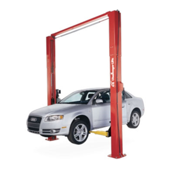
Two Post
Surface Mounted Lift
M
ODEL
10,000
LBS
2500
LBS
sales@challengerlifts.com
/
502-625-0700 Fax 502-587-1933
READ THIS MANUAL COMPLETELY BEFORE
INSTALLING or OPERATING LIFT
& M
AINTENANCE
E10
. C
APACITY
.
A
PER
RM
Web site:
www.challengerlifts.com
M
ANUAL
Rev. 01/07/16
Advertisement
Table of Contents

Related Manuals for Challenger Lifts E10


Summary of Contents for Challenger Lifts E10
- Page 1 & M NSTALLATION PERATION AINTENANCE ANUAL Two Post Surface Mounted Lift ODEL 10,000 APACITY 2500 200 Cabel Street, P.O. Box 3944 Louisville, Kentucky 40201-3944 Email: Web site: sales@challengerlifts.com www.challengerlifts.com Office 800-648-5438 502-625-0700 Fax 502-587-1933 IMPORTANT: READ THIS MANUAL COMPLETELY BEFORE INSTALLING or OPERATING LIFT Rev.
-
Page 2: General Specifications
Model E10 Installation, Operation and Maintenance ENERAL PECIFICATIONS See Figure 1 E10 w/ 2 Ft. Ext. Kit Rise Height (Screw Pads Highest Position) 74 3/4" (1899 mm) Overall Height 143 7/8" 167 7/8" (3655 mm) (4264 mm) Overall Width 131 3/4"... -
Page 3: Vertical Clearance
Model E10 Installation, Operation and Maintenance ERTICAL LEARANCE EAD ENTIRE MANUAL BEFORE ASSEMBLING INSTALLING OPERATING OR SERVICING THIS Check the height of the area where the lift is to be EQUIPMENT installed. Clearance should be calculated based on ROPER MAINTENANCE AND INSPECTION IS the full raised height of the lift. -
Page 4: Installation
Model E10 Installation, Operation and Maintenance ECEIVING NSTALLATION The shipment should be thoroughly inspected as MPORTANT Always wear safety glasses while installing lift. soon as it is received. The signed bill of lading is OOLS MINIMUM REQUIRED acknowledgement by the carrier of receipt in good a. - Page 5 Model E10 Installation, Operation and Maintenance YNCHRONIZER ABLES NCHORING 14) Manually raise each carriage into the second 4) The anchor bolts must be installed at least 8” lock position. from any crack, edge, or expansion joint. 15) At upper beam...
- Page 6 Model E10 Installation, Operation and Maintenance OLUMN XTENSIONS 19) Hoses, cables, and limit switch cord should be routed as shown in Fig. 5. Fig. 6 – Hose Routing 24) Beginning on the idler side, attach the idler extension hose to the cylinder elbow fitting (This hose has a male fitting on one end and is removed for reduced height installations).
-
Page 7: Lock Release
Model E10 Installation, Operation and Maintenance ELEASE 34) Check arm stop engagement by fully extending each arm. Properly installed arm stop hardware 28) Install Lock Release Stud and Knob to the Powre will prevent arm from becoming over- extended Column Lock using one M10 Nut. - Page 8 Model E10 Installation, Operation and Maintenance OLUMN ECAL LACEMENT YNCHRONIZING ABLES 42) Clean the surface of the columns before placing 49) Raise lift and insure carriages lower into same the decals. lock position. 43) Apply the Safety Decals (Pg. 3) 48” above the...
- Page 9 Model E10 Installation, Operation and Maintenance Wiring Diagram FIELD FOR SINGLE PHASE CONECTIONS (Normally Open) FOR THREE PHASE FACTORY WIRED FOR 208−240V RECONNECTIONS FOR 440−480V Fig 8 – Electrical Wiring Diagram Page 9 Rev. 01/07/16 E10-IOM-A.
-
Page 10: Operation Procedure
Model E10 Installation, Operation and Maintenance Requirements Operation, Inspection PERATION ROCEDURE Maintenance; and in the case of frame engaging lift, AFETY OTICES AND ECALS ALI/LP-GUIDE, Vehicle Lifting Points/Quick Reference Guide for Frame Engaging Lifts; in a This product is furnished with graphic safety... -
Page 11: Lifting A Vehicle
Model E10 Installation, Operation and Maintenance IFTING A EHICLE 5) Continue to lower the vehicle until the carriages stop against the base plate. Retract the 1) Insure that the lifting arms are parked, out to full extension arms, and park them. -
Page 12: Maintenance
Check for loose or broken parts. Check hydraulic system for fluid leaks. Check adapters for damage or excessive wear. Replace as required with genuine Challenger Lifts parts. Check lock release activation. When properly adjusted, the idler column lock should rest firmly... - Page 13 Model E10 Installation, Operation and Maintenance Parts Breakdown Page 13 Rev. 01/07/16 E10-IOM-A.
- Page 14 Model E10 Installation, Operation and Maintenance Page 14 Rev. 01/07/16 E10-IOM-A.
- Page 15 Bolt M8 x 25 IMPORTANT Replace all worn, damaged, or broken parts with parts approved by Challenger Lifts, Inc. or with parts meeting Challenger Lifts Inc. specifications. Contact your local Challenger Lifts parts distributor for pricing and availability. Call Challenger Lifts at (502) 625-0700 for the distributor in your area.
Need help?
Do you have a question about the E10 and is the answer not in the manual?
Questions and answers