Table of Contents
Advertisement
Quick Links
One Technology Way • P.O. Box 9106 • Norwood, MA 02062-9106, U.S.A. • Tel: 781.329.4700 • Fax: 781.461.3113 • www.analog.com
Evaluating the
FEATURES
Fully featured evaluation board for the
PC control in conjunction with Analog Devices, Inc.,
system demonstration platform (EVAL-SDP-CB1Z)
PC software for control and data analysis (time domain)
EVALUATION KIT CONTENTS
EVAL-AD4111SDZ evaluation board
SOFTWARE NEEDED
AD411x Eval+ evaluation software
EQUIPMENT NEEDED
EVAL-SDP-CB1Z
system demonstration platform
DC signal source
PC running Windows® with USB 2.0 port
PLEASE SEE THE LAST PAGE FOR AN IMPORTANT
WARNING AND LEGAL TERMS AND CONDITIONS.
Arrow.com.
Downloaded from
AD4111
with ±10 V and 0 mA to 20 mA Inputs and Integrated Analog
Front End for Industrial Automation Systems
AD4111
SDP-B
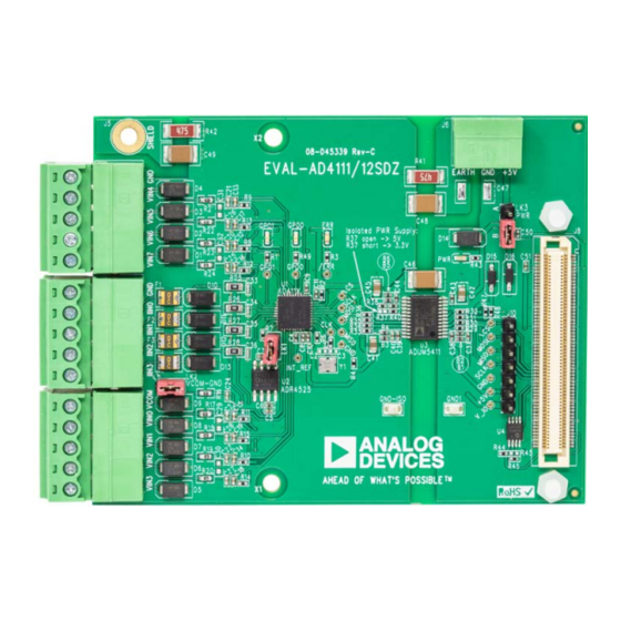
EVALUATION BOARD PHOTOGRAPH
EVAL-AD4111SDZ
GENERAL DESCRIPTION
The EVAL-AD4111SDZ is a full featured evaluation board that
can be used to evaluate all the features of the AD4111. The
AD4111
is a 24-bit, 31.25 kSPS analog-to-digital converter
(ADC) with a ±10 V input voltage range (eight single-ended or
four differential channels) with open wire detection and
four current channels operating from 0 mA to 20 mA. All
channels have on-board overvoltage and overcurrent protection.
The EVAL-AD4111SDZ board includes voltage reference,
power, and data insulation and can be connected to the Analog
Devices, Inc.,
SDP-B
SDP-CB1Z). The
SDP-B
a USB port and can provide power for the EVAL-AD4111SDZ
board from the PC USB port.
The AD411X Eval+ evaluation software configures the
device functionality and provides open wire detection, dc time
domain analysis in the form of waveform graphs, histograms,
and associated noise analysis for ADC performance evaluation.
Full specifications for the
data sheet, which must be consulted in conjunction with this
user guide when working with this evaluation board.
Figure 1.
Rev. A | Page 1 of 26
User Guide
UG-1124
system demonstration platform
board provides connection to a PC via
AD4111
are available in the
(EVAL-
AD4111
AD4111
Advertisement
Table of Contents

Related Manuals for Analog Devices EVAL-AD4111SDZ


Summary of Contents for Analog Devices EVAL-AD4111SDZ
-
Page 1: Features
SDP-B board provides connection to a PC via EVAL-SDP-CB1Z system demonstration platform a USB port and can provide power for the EVAL-AD4111SDZ DC signal source board from the PC USB port. PC running Windows® with USB 2.0 port The AD411X Eval+ evaluation software configures the... -
Page 2: Table Of Contents
Changes to Figure 2 ................3 Changes to Figure 20 Caption, Register Tree Section, Register Changed Eval-AD4111SDZ Eval+ Quick Start Guide Section to Tree Search Section, Register and Bit Field Control Section, and EVAL-AD4111SDZ Quick Start Guide Section ......4 Save and Load Section .............. -
Page 3: Evaluation Board Block Diagram
EVAL-AD4111SDZ User Guide UG-1124 EVALUATION BOARD BLOCK DIAGRAM Figure 2. Evaluation Board Block Diagram Rev. A | Page 3 of 26 Arrow.com. Arrow.com. Arrow.com. Downloaded from Downloaded from Downloaded from... -
Page 4: Eval-Ad4111Sdz Quick Start Guide
USB port of the PC. Install the AD411x Eval+ software (available for download Connect the dc signal source to the selected voltage input from the EVAL-AD4111SDZ product page). Restart the PC (for example, VIN0 and VIN1 for differential input). after installation. -
Page 5: Evaluation Board Hardware
Full together using the plastic screw and washer set included in details on the EVAL-AD4111SDZ are available on the product the evaluation board kit to connect the boards firmly together. page on the Analog Devices website. -
Page 6: Serial Interface
REFERENCE OPTIONS user to develop their own C code rather than using the provided The EVAL-AD4111SDZ includes an external 2.5 V reference, evaluation software. the ADR4525ARZ. By default, LK1 is inserted, connecting the To operate the EVAL-AD4111SDZ in standalone mode, external reference to the REF+ pin of the AD4111. -
Page 7: Changes To Figure 5 Through Figure 7
EVAL-AD4111SDZ User Guide UG-1124 EVALUATION BOARD SOFTWARE SOFTWARE INSTALLATION PROCEDURES The EVAL-AD4111SDZ evaluation kit includes a link to the software that must be installed before using the EVAL-AD4111SDZ. There are two parts to the installation: AD411x Eval+ software installation ... -
Page 8: Changes To Figure 8, Figure 9 Caption Through Figure 11 Caption, And Installing The Eval+ Dependencies Drivers Section
Figure 8. AD411x Eval+ Software Installation: Indicating When the Installation Is Complete Figure 10. Analog Devices Eval+ Dependencies Setup: Installing the Eval+ Dependencies Drivers Completing the Drivers Setup Wizard After the installation of the evaluation software is complete, a Before using the evaluation board, restart the PC. -
Page 9: Moved Figure 15
AD4111 register map. From the Start menu, click Programs > Analog Devices > When operating in advanced mode, the user must consult AD411x Eval+ > AD411x Eval+. The dialog box in with and have a good understanding of the... -
Page 10: Change To Figure 16 Caption And Figure 17 Caption
UG-1124 EVAL-AD4111SDZ User Guide Figure 16. Configuration Tab of the AD4111 Eval+ Software in Quickstart Mode Figure 17. Configuration Tab of the AD4111 Eval+ Software in Advanced Mode Rev. A | Page 10 of 26 Arrow.com. Arrow.com. Arrow.com. Arrow.com. Arrow.com. -
Page 11: Changes To Overview Of The Main Window Section, Output Data Rate (Odr) And Measurement Time Section, And Reset Section
AVSS (Label 11 in Figure 16). The external reference on the Resolution shown in the Noise Analysis (see Figure 18). EVAL-AD4111SDZ is set to 2.5 V by using an ADR4525. If Output Data Rate (ODR) and Measurement Time bypassing the... -
Page 12: Waveform Tabs
UG-1124 EVAL-AD4111SDZ User Guide Figure 18. Voltage Waveform Tab of the AD4111 Eval+ Software WAVEFORM TABS Samples control. If Sampling Mode is set to Continuous mode, the ADC continuously returns samples until stopped by the The AD411x Eval+ software has three different waveform tabs: user. -
Page 13: Changes To Device Error Section, Figure 19 Caption, And Analysis Input Section
EVAL-AD4111SDZ User Guide UG-1124 Device Error Noise Analysis The Device Error indicator (Label 22 in Figure 18) illuminates The Noise Analysis section (Label 24 in Figure 18) displays the in the waveform tabs when a cyclic redundancy check (CRC) results of the noise analysis for the selected analysis input, error or an error in the ADC is detected. -
Page 14: Histogram Tab
UG-1124 EVAL-AD4111SDZ User Guide Figure 19. Histogram Tab of the AD4111 Eval+ Software HISTOGRAM TAB Noise Analysis The Noise Analysis section (Label 28 in Figure 19) displays the The Histogram tab generates a histogram using the gathered results of the noise analysis for the selected analysis input, samples and processes the data, calculating the peak-to-peak including both noise and resolution measurements. -
Page 15: Register Map Tab (Advanced Mode Only)
EVAL-AD4111SDZ User Guide UG-1124 Figure 20. Registers Tab of the AD4111 Eval+ Software REGISTER MAP TAB (ADVANCED MODE ONLY) Documentation The Documentation field (Label 39 in Figure 20) contains the Register Tree documentation for the register or the bit field selected. This... -
Page 16: Evaluation Board Schematics And Artwork
UG-1124 EVAL-AD4111SDZ User Guide EVALUATION BOARD SCHEMATICS AND ARTWORK Figure 21. AD4111 Schematic on the EVAL-AD4111SDZ Rev. A | Page 16 of 26 Arrow.com. Arrow.com. Arrow.com. Arrow.com. Arrow.com. Arrow.com. Arrow.com. Arrow.com. Arrow.com. Arrow.com. Arrow.com. Arrow.com. Arrow.com. Arrow.com. Arrow.com. Arrow.com. Downloaded from... -
Page 17: Changes To Figure 22
EVAL-AD4111SDZ User Guide UG-1124 Figure 22. Voltage Input Front End Schematic Rev. A | Page 17 of 26 Arrow.com. Arrow.com. Arrow.com. Arrow.com. Arrow.com. Arrow.com. Arrow.com. Arrow.com. Arrow.com. Arrow.com. Arrow.com. Arrow.com. Arrow.com. Arrow.com. Arrow.com. Arrow.com. Arrow.com. Downloaded from Downloaded from Downloaded from... - Page 18 UG-1124 EVAL-AD4111SDZ User Guide CURRENT INPUTS J4-9 J3-4 IIN0 180R 2R8 - 50R MF-USMF005-2 470pF 50 mA GND_ISO J4-8 J3-3 IIN1 180R 2R8 - 50R MF-USMF005-2 470pF 50 mA J4-7 GND_ISO J3-2 IIN2 180R 2R8 - 50R MF-USMF005-2 470pF 50 mA...
-
Page 19: Change To Figure 24 Caption
EVAL-AD4111SDZ User Guide UG-1124 Figure 24. System Demonstration Platform Connector Schematic Rev. A | Page 19 of 26 Arrow.com. Arrow.com. Arrow.com. Arrow.com. Arrow.com. Arrow.com. Arrow.com. Arrow.com. Arrow.com. Arrow.com. Arrow.com. Arrow.com. Arrow.com. Arrow.com. Arrow.com. Arrow.com. Arrow.com. Arrow.com. Arrow.com. Downloaded from Downloaded from... -
Page 20: Changes To Figure 25
UG-1124 EVAL-AD4111SDZ User Guide Figure 25. Insulation and Power Supply Schematic Rev. A | Page 20 of 26 Arrow.com. Arrow.com. Arrow.com. Arrow.com. Arrow.com. Arrow.com. Arrow.com. Arrow.com. Arrow.com. Arrow.com. Arrow.com. Arrow.com. Arrow.com. Arrow.com. Arrow.com. Arrow.com. Arrow.com. Arrow.com. Arrow.com. Arrow.com. Downloaded from... -
Page 21: Changes To Figure 26
EVAL-AD4111SDZ User Guide UG-1124 Figure 26. Printed Circuit Board (PCB), Top Rev. A | Page 21 of 26 Arrow.com. Arrow.com. Arrow.com. Arrow.com. Arrow.com. Arrow.com. Arrow.com. Arrow.com. Arrow.com. Arrow.com. Arrow.com. Arrow.com. Arrow.com. Arrow.com. Arrow.com. Arrow.com. Arrow.com. Arrow.com. Arrow.com. Arrow.com. Arrow.com. Downloaded from... -
Page 22: Changes To Figure 27
UG-1124 EVAL-AD4111SDZ User Guide Figure 27. Component Side, Silkscreen, Top Rev. A | Page 22 of 26 Arrow.com. Arrow.com. Arrow.com. Arrow.com. Arrow.com. Arrow.com. Arrow.com. Arrow.com. Arrow.com. Arrow.com. Arrow.com. Arrow.com. Arrow.com. Arrow.com. Arrow.com. Arrow.com. Arrow.com. Arrow.com. Arrow.com. Arrow.com. Arrow.com. Arrow.com. Downloaded from... -
Page 23: Changes To Figure 28
EVAL-AD4111SDZ User Guide UG-1124 Figure 28. Layer 1, Component Side Rev. A | Page 23 of 26 Arrow.com. Arrow.com. Arrow.com. Arrow.com. Arrow.com. Arrow.com. Arrow.com. Arrow.com. Arrow.com. Arrow.com. Arrow.com. Arrow.com. Arrow.com. Arrow.com. Arrow.com. Arrow.com. Arrow.com. Arrow.com. Arrow.com. Arrow.com. Arrow.com. Arrow.com. Arrow.com. -
Page 24: Changes To Figure 29
UG-1124 EVAL-AD4111SDZ User Guide Figure 29. Layer 2, Solder Side Rev. A | Page 24 of 26 Arrow.com. Arrow.com. Arrow.com. Arrow.com. Arrow.com. Arrow.com. Arrow.com. Arrow.com. Arrow.com. Arrow.com. Arrow.com. Arrow.com. Arrow.com. Arrow.com. Arrow.com. Arrow.com. Arrow.com. Arrow.com. Arrow.com. Arrow.com. Arrow.com. Arrow.com. Arrow.com. -
Page 25: Ordering Information
EVAL-AD4111SDZ User Guide UG-1124 ORDERING INFORMATION BILL OF MATERIALS Table 3. Bill of Materials Reference Designator Description Manufacturer Part Number B1 to B6 B0402, 1800 Ω at 100 MHz, 200 mA Murata BLM15HD182SN1D C0402, do not place Not applicable Not applicable... -
Page 26: Added I 2 C Note
By using the evaluation board discussed herein (together with any tools, components documentation or support materials, the “Evaluation Board”), you are agreeing to be bound by the terms and conditions set forth below (“Agreement”) unless you have purchased the Evaluation Board, in which case the Analog Devices Standard Terms and Conditions of Sale shall govern. Do not use the Evaluation Board until you have read and agreed to the Agreement.
Need help?
Do you have a question about the EVAL-AD4111SDZ and is the answer not in the manual?
Questions and answers