Table of Contents
Advertisement
Quick Links
Evaluating the AD4052 Compact, Low Power, 16-Bit, 2 MSPS Easy Drive SAR ADC
FEATURES
Full featured evaluation board for the AD4052 with a USB power
►
solution
Single differential channel and common-mode input available
►
through SMA connectors
Out of the box evaluation experience with the SDP-K1
►
PC software (ACE plugin) for control and data analysis of the
►
time and frequency domains
Compatible with other Arduino form factor controller boards
►
EQUIPMENT NEEDED
PC with Windows 7 or later operating system
►
SDP-K1 controller board and accompanying USB cable
►
Precision signal generator (see the
►
section)
SOFTWARE NEEDED
ACE
evaluation software
►
AD4052
ACE plugin
from the plugin manager (see the
►
Installation Procedure
section)
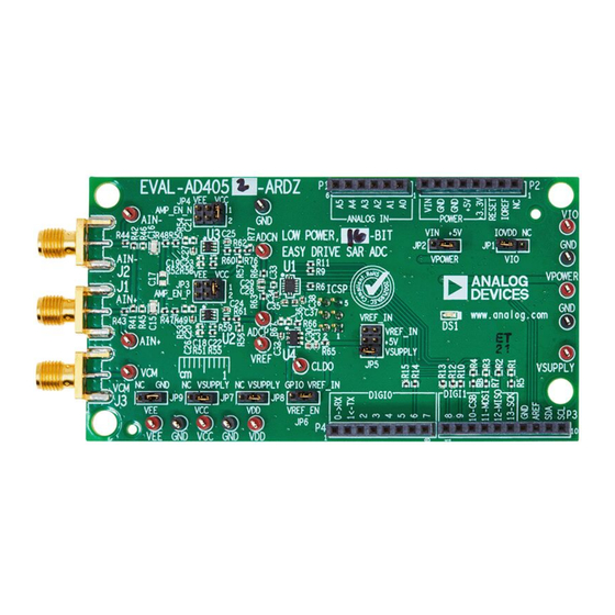
EVALUATION BOARD PHOTOGRAPH
PLEASE SEE THE LAST PAGE FOR AN IMPORTANT
WARNING AND LEGAL TERMS AND CONDITIONS.
Evaluation Board Hardware
Software
Figure 1. EVAL-AD4052-ARDZ Evaluation Board Photograph
User Guide | EVAL-AD4052
USEFUL LINKS AND RESOURCES
AD4052
product page
►
EVAL-AD4052-ARDZ
product page
►
ACE Installer
►
GENERAL DESCRIPTION
The EVAL-AD4052-ARDZ enables quick and easy evaluation of
the performance and features of the AD4052. The AD4052 is a
compact, low power, 16-bit Easy Drive successive approximation
register (SAR) analog-to-digital converter (ADC).
The primary controller board for the EVAL-AD4052-ARDZ is the
SDP-K1. The EVAL-AD4052-ARDZ conforms to the Arduino
Shield mechanical and electrical standards to interface with the
SDP-K1, in addition to various software development kits from other
manufacturers.
The AD4052 evaluation solution includes the AD4052 industrial
input and output (IIO) firmware application drivers for device con-
figuration and ADC data capture and the AD4052 ACE plugin
graphical user interface (GUI) for performance evaluation.
UG-2222
®
Uno
Rev. 0 | 1 of 19
Advertisement
Table of Contents

Related Manuals for Analog Devices AD4052


Summary of Contents for Analog Devices AD4052
-
Page 1: Features
User Guide | EVAL-AD4052 UG-2222 Evaluating the AD4052 Compact, Low Power, 16-Bit, 2 MSPS Easy Drive SAR ADC FEATURES USEFUL LINKS AND RESOURCES Full featured evaluation board for the AD4052 with a USB power AD4052 product page ► ► solution... -
Page 2: Table Of Contents
General Description..........1 Software Installation Procedure....... 13 Evaluation Board Photograph........1 Installing the ACE Evaluation Software....13 Quick Start Guide..........3 Installing the AD4052 ACE Plugin....13 Hardware Setup..........3 Launching the Software........14 Evaluation Board Hardware........5 Board View and Firmware Selection....14 Hardware Overview..........5 Chip View............ -
Page 3: Quick Start Guide
+5 V position. This position connects the EVAL-AD4052-ARDZ power management circuitry to the +5 V pin on the Arduino Uno This section details how to set up the AD4052 and SDP-K1 boards power header. for use with the AD4052 ACE plugin. Refer to the... - Page 4 If no signal generator is available, a jumper cable between the VREF and VCM test points can be used to bias the AD4052 analog inputs to VREF. This is preferred over connecting the amplifier inputs to GND, because the amplifier VEE rails are connected to GND by default.
-
Page 5: Evaluation Board Hardware
SDP-K1 input power source down to a ► Figure 7 shows a simplified block diagram of the EVAL-AD4052- 3.3 V rail to power the AD4052 and other analog components ARDZ and Figure 8 Figure 9 show the location of the primary These companion components were selected to simplify evaluation circuit blocks on the board. - Page 6 User Guide EVAL-AD4052 EVALUATION BOARD HARDWARE Figure 8. EVAL-AD4052-ARDZ Evaluation Board Circuitry Locations Top Side Figure 9. EVAL-AD4052-ARDZ Evaluation Board Circuitry Locations Bottom Side analog.com Rev. 0 | 6 of 19...
-
Page 7: Connectors And Sockets
Arduino Uno mechanical specification only. The pins writing data, a CNV input for initiating conversions, and two GPIOs on this header are not routed out as signals to the EVAL-AD4052- with multiple functions. The AD4052 digital interface signals are ARDZ. -
Page 8: Power Supplies
ARDZ as named in the schematic. Each power rail can be meas- default configuration, the EVAL-AD4052-ARDZ analog circuitry is ured or driven with external supplies via the test points labeled in powered by an on-board 3.3 V supply and the AD4052 I/O log- the table. See the Hardware and Link Options section for details ic voltage is supplied directly from the controller board’s IOREF... -
Page 9: Voltage Reference Circuit
AD4052 data sheet. By default, the MAX6070 is powered by the 3.3 V analog rail. A 2.2 uF V decoupling capacitor (C34) is located next to the AD4052 REF pin to ensure a stable 2.5 V V voltage during the conversion time of the SAR ADC core. - Page 10 MAX44260 amplifiers. then the AD4052 will reject some portion of it depending on the Figure 15 gives an example with a 2.5 V V and amplifiers in bandwidth of the device.
- Page 11 User Guide EVAL-AD4052 EVALUATION BOARD HARDWARE Figure 16. Biased Differential Signal Generator Example analog.com Rev. 0 | 11 of 19...
-
Page 12: Hardware And Link Options
EVALUATION BOARD HARDWARE HARDWARE AND LINK OPTIONS Table 4 details each of the optional jumper and link options present on the EVAL-AD4052-ARDZ with a brief description of the default and secondary positions and functions. Table 4. Jumper and Link Options and Descriptions... -
Page 13: Evaluation Board Software
ARDZ evaluation kit page. Install the software on a PC before using the EVAL-AD4052-ARDZ kit. Download the AD4052 ACE plugin from the EVAL-AD4052-ARDZ product page or from the ACE plugin manager. Perform the following steps to complete the installation process: 1. -
Page 14: Launching The Software
23). Click OK and ACE will begin loading the generic tinyiiod firmware onto the SDP-K1. (Note that after connecting to the EVAL-AD4052-ARDZ, the ACE plugin will need to load an AD4052 specific firmware build, as described in the Board View and Firmware Selection section). -
Page 15: Chip View
User Guide EVAL-AD4052 EVALUATION BOARD SOFTWARE CHIP VIEW Hover over the AD4052 symbol in the Board View and double click to enter the Chip View (see Figure 25). Figure 25. AD4052 Plugin Chip View analog.com Rev. 0 | 15 of 19... -
Page 16: Analysis View
The Waveform graph shows each successive sample of the ANALYSIS VIEW AD4052 output. The user can zoom in on and pan over the Wave- Click Proceed to Analysis to navigate to the AD4052 Analysis form graph using the embedded waveform tool bar located above window. - Page 17 User Guide EVAL-AD4052 EVALUATION BOARD SOFTWARE The Histogram graph displays the number of hits per code within Histogram Tab the sampled data. Use this graph for DC analysis as it indicates the The Histogram tab contains the histogram graph and the Results noise performance of the device.
- Page 18 (THD) measurements, as well as the major When performing an FFT analysis, the RESULTS pane shows harmonics contributing to the THD performance, are shown as well. the noise and distortion performance of the AD4052. The sig- Figure 28. FFT Tab analog.com...
-
Page 19: Notes
Evaluation Board until you have read and agreed to the Agreement. Your use of the Evaluation Board shall signify your acceptance of the Agreement. This Agreement is made by and between you (“Customer”) and Analog Devices, Inc. (“ADI”), with its principal place of business at Subject to the terms and conditions of the Agreement, ADI hereby grants to Customer a free, limited, personal, temporary, non-exclusive, non-sublicensable, non-transferable license to use the Evaluation Board FOR EVALUATION PURPOSES ONLY.
Need help?
Do you have a question about the AD4052 and is the answer not in the manual?
Questions and answers