Pfeiffer Vacuum HiPace Operating Instructions Manual
Hide thumbs
Also See for HiPace:
- Operating instructions manual (62 pages) ,
- Operating instructions manual (39 pages) ,
- Operating instructions manual (44 pages)
Table of Contents
Advertisement
Advertisement
Table of Contents

Related Manuals for Pfeiffer Vacuum HiPace


Summary of Contents for Pfeiffer Vacuum HiPace
- Page 1 OPERATING INSTRUCTIONS Translation of the Original HIPACE Air cooling...
- Page 2 These operating instructions describe all models and variants of your product. Note that your product may not be equipped with all features described in this document. Pfeiffer Vacuum constantly adapts its products to the latest state of the art without prior notice. Please take into account that online operating instructions can deviate from the printed operating instructions supplied with your product.
-
Page 3: Table Of Contents
Installation Connecting the air cooling for 24 V DC Connecting the air cooling for 115/230 V AC 4.2.1 Connecting the air cooling for HiPace 60 P, HiPace 80, and Split- Flow 50 4.2.2 Establishing mains connection Connecting the air cooling, 24 V DC for TeleTC... - Page 4 List of tables List of tables Tbl. 1: Applicable documents Tbl. 2: Air cooling versions Tbl. 3: Stickers on the product Tbl. 4: Permissible ambient and operating conditions Tbl. 5: Parameter settings in the electronic drive unit of the turbopump Tbl.
- Page 5 Position of the sticker on the product Fig. 2: Layout of air cooling Fig. 3: Connecting the air cooling to HiPace 30, HiPace 80, HiPace 60 P and Split- Flow 50 Fig. 4: Connecting the air cooling to HiPace 300 with TC 110/TC 120 Fig.
-
Page 6: About This Manual
Keep the manual for future consultation. 1.1 Validity This operating instructions is a customer document of Pfeiffer Vacuum. The operating instructions de- scribe the functions of the named product and provide the most important information for the safe use of the device. The description is written in accordance with the valid directives. The information in this op- erating instructions refers to the product's current development status. -
Page 7: Pictographs
About this manual Sequence of multi-part action steps The numerical list indicates an action with multiple necessary steps. 1. Step 1 2. Step 2 3..1.3.2 Pictographs Pictographs used in the document indicate useful information. Note 1.3.3 Stickers on the product This section describes all the stickers on the product along with their meaning. -
Page 8: Safety
Safety 2 Safety 2.1 General safety information The following 4 risk levels and 1 information level are taken into account in this document. DANGER Immediately pending danger Indicates an immediately pending danger that will result in death or serious injury if not observed. ►... -
Page 9: Safety Precautions
Permissible ambient and operating conditions 2.5 Proper use ► Use the air cooling exclusively for the cooling of Pfeiffer Vacuum turbopumps in ambient tempera- tures up to a max. 35 °C. ► Adhere to the installation, commissioning, operating, and maintenance instructions. -
Page 10: Personnel Qualification
The work described in this document may only be carried out by persons who have appropriate profes- sional qualifications and the necessary experience or who have completed the necessary training as provided by Pfeiffer Vacuum. Training people 1. Train the technical personnel on the product. -
Page 11: Product Description
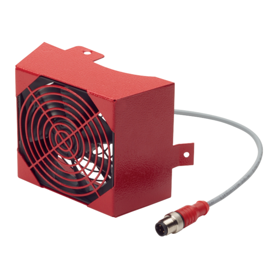
Control cable power supply plug 2 Air cooling 3.2 Identifying the product ► To ensure clear identification of the product when communicating with Pfeiffer Vacuum, always keep all of the information on the rating plate to hand. 3.3 Scope of delivery The scope of delivery includes the following parts: ●... -
Page 12: Installation
● Allen key, WAF 2.5 ● Allen key, WAF 3 Fig. 3: Connecting the air cooling to HiPace 30, HiPace 80, HiPace 60 P and SplitFlow 50 1 Control cable connector plug Hexagon head set screw 2 15-pin D Sub plug on multi-function connection "X3"... -
Page 13: Fig. 5: Connecting The Air Cooling To Hipace 300 With Tc 400
Installation Fig. 5: Connecting the air cooling to HiPace 300 with TC 400 1 Control cable connector plug Air cooling 2 Pump bottom part Countersunk screw 3 Interior hexagon socket screw Fig. 6: Connecting the air cooling to HiPace 350 and HiPace 450... -
Page 14: Connecting The Air Cooling For 115/230 V Ac
Installation Fig. 7: Connecting the air cooling to HiPace 400, HiPace 700 and HiPace 800 1 Interior hexagon socket screw Pump bottom part 2 Air cooling Countersink screw 3 Control cable connector plug Procedure 1. Attach the air cooling to the pump bottom part using the screws from the mounting kit. -
Page 15: Connecting The Air Cooling For Hipace 60 P, Hipace 80, And Split
Installation 4.2.1 Connecting the air cooling for HiPace 60 P, HiPace 80, and SplitFlow 50 Prerequisites ● Turbopump switched off and flooded Required tools ● Allen key, WAF 2.5 ● Allen key, WAF 3 Fig. 8: Fitting the mounting bracket for air cooling... -
Page 16: Establishing Mains Connection
4.3 Connecting the air cooling, 24 V DC for TeleTC Recommended use of air cooling on the electronic drive unit With commensurate ambient temperatures, Pfeiffer Vacuum recommends that an addition- al air cooling be fitted on the TC of the turbopump. - Page 17 Installation Procedure 1. Attach the air cooling at the upper bore of the electronic drive unit using the installation materials (separate package) and the interior hexagon socket screw. 2. Screw the control cable of the air cooling valve into a vacant accessory connection on the elec- tronic drive unit.
-
Page 18: Operation
Important settings and function-related variables are programmed ex factory as parameters in the vac- uum pump electronic drive unit. Each parameter has a three-digit number and a description. Parameter- driven operation and control is supported via Pfeiffer Vacuum displays and control units, or externally via RS-485 using Pfeiffer Vacuum protocol. -
Page 19: Service Solutions By Pfeiffer Vacuum
We are always focused on perfecting our core competence – servicing of vacuum components. Once you have purchased a product from Pfeiffer Vacuum, our service is far from over. This is often exactly where service begins. Obviously, in proven Pfeiffer Vacuum quality. - Page 20 Service solutions by Pfeiffer Vacuum 5. Prepare the product for transport in accordance with the provisions in the contamination declaration. a) Neutralize the product with nitrogen or dry air. b) Seal all openings with blind flanges, so that they are airtight.
-
Page 21: Technical Data And Dimensions
Air Cooling Part number PM Z01 300 PM Z01 301 PM Z01 348 Pump HiPace 60 | HiPace 80 | Split- HiPace 300/450 HiPace 30 Flow 50/80 Electronic drive unit TC 110, TC 120, TCP 350 TC 110, TC 120,... -
Page 22: Dimensions
Air Cooling Air Cooling Part number PM Z01 343 PM Z01 344 Pump HiPace 60 P | HiPace 80 | Split- HiPace 60 P | HiPace 80 | Split- Flow 50/80 Flow 50/80 Mains connection: Voltage 230 V 115 V Tbl. -
Page 23: Fig. 15: Dimensions Pm Z01 304 A | Pm Z01 364 A
Technical data and dimensions 56.9 Fig. 15: Dimensions PM Z01 304 A | PM Z01 364 A 35.5 Fig. 16: Dimensions PM Z01 373 | PM Z01 374 Dimensions in mm 23/26... -
Page 24: Declaration Of Conformity
Declaration of conformity Declaration for product(s) of the type: Air cooling HiPace 30 – 800 SplitFlow 30 – 80 We hereby declare that the listed product satisfies all relevant provisions of the following European Directives. Electromagnetic compatibility 2014/30/EU Low voltage 2014/35/EC... - Page 25 25/26...
Need help?
Do you have a question about the HiPace and is the answer not in the manual?
Questions and answers