Pfeiffer Vacuum HiPace 2300 Operating Instructions Manual
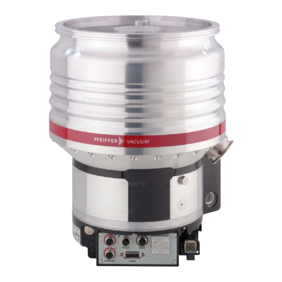
Turbopump
Hide thumbs
Also See for HiPace 2300:
- Operating instructions manual (76 pages) ,
- Operating instructions manual (26 pages) ,
- Operating instructions manual (84 pages)

Related Manuals for Pfeiffer Vacuum HiPace 2300


Summary of Contents for Pfeiffer Vacuum HiPace 2300
- Page 1 OPERATING INSTRUCTIONS Translation of the original instructions HIPACE 2300 Turbopump...
-
Page 2: Table Of Contents
Table of contents Table of contents About this manual ..........4 1.1 Validity. - Page 3 13.3 HiPace 2300 C / HiPace 2300 U C ......43...
-
Page 4: About This Manual
About this manual Validity This operating manual is for customers of Pfeiffer Vacuum. It describes the functioning of the designated product and provides the most important information for safe use of the unit. The description follows applicable EU guidelines. All information provided in this operating manual refers to the current state of the product's development. -
Page 5: Pictographs
About this manual 1.2.2 Pictographs Prohibition of an action or activity in connection with a source of danger, the disregarding of which may result in serious accidents Warning of a displayed source of danger in connection with operation of the unit or equipment Command to perform an action or task associated with a source of dan- ger, the disregarding of which may result in serious accidents Important information about the product or this document... -
Page 6: Safety
Installation and operation of accessories Pfeiffer Vacuum pumps can be equipped with a series of adapted accessories. The in- stallation, operation and maintenance of connected devices are described in detail in the operating instructions of the individual components. -
Page 7: Protective Equipment
Safety ● Do not carry out any unauthorized modifications or conversions to the pump. ● When returning the turbopump observe the shipping instructions. Protective equipment Determined situations concerning the handling of vacuum pumps require wearing of per- sonal protective equipment. The owner, respectively the employer are obligated to pro- vide an adequate equipment to any operating persons. -
Page 8: Improper Use
Safety Improper use Improper use will cause all claims for liability and warranties to be forfeited. Improper use is defined as usage for purposes deviating from those mentioned above, especially: ● transport, installation or operation of the pump in invalid orientation ●... -
Page 9: Transport And Storage
60° Fig. 1: Transport of HiPace 2300 Fig. 2: Transport of HiPace 2300 U WARNING Danger from falling and swinging loads! When lifting the pump there is a danger of falling parts. Make sure that there are no persons under the suspended load. -
Page 10: Product Description
Made in Germany Fig. 3: Example for a rating plate 4.1.3 Variants ● HiPace 2300 ● HiPace 2300 C, corrosive gas version ● HiPace 2300 U, for upside-down installation orientation ● HiPace 2300 U C, for upside-down installation orientation and corrosive gases... -
Page 11: Function
● Screw-in nozzle (2x) with seal ring for cooling water connection ● Eye bolts ● Operating instructions Function The turbopumps HiPace 2300 form a complete unit together with the electronic drive unit. The voltage is supplied via the integrated power supply pack. Fig. 4: HiPace 2300 with TC 1200... -
Page 12: Range Of Application
Product description Range of application The pump HiPace 2300 must be installed and operated under the following ambient con- ditions: Installation location weather protected (indoors) Protection class IP54 Temperature +5 °C to +40 °C max. 80 %, at T 31 °C, to max. 50 % at T 40 °C... -
Page 13: Installation
Observe the permitted venting rates (max. 15 hPa/s). Installation and operation of accessories Pfeiffer Vacuum pumps can be equipped with a series of adapted accessories. The in- stallation, operation and maintenance of connected devices are described in detail in the operating instructions of the individual components. -
Page 14: Set-Up
5.2.2 Use of a splinter shield or protection screen Pfeiffer Vacuum centering rings with splinter shield or protection screen in the high vac- uum flange protect the turbopump against foreign bodies coming from the chamber. Thus, the pumping speed of the pump is reduced. -
Page 15: Mounting Orientation
Installation Mounting orientation NOTICE Observe type-specific mounting orientations! Incorrect mounting orientations result in contamination of the process vacuum or dam- age to the pump. Pay attention to the properties after the model designation on the name plate! Observe the pictographs on the pump housing! ... -
Page 16: Connecting The High Vacuum Side
Twisting or tearing-off is possible in case the rotor is suddenly blocked due to the fas- tening of pumps on a vacuum chamber with different flange variants. Use only the correct mounting kit from Pfeiffer Vacuum. Pfeiffer Vacuum will not accept any liability for all damages resulting from impermis- sible fastening. DANGER... -
Page 17: Installation Of Iso-K Flange With Iso-F Flange
"stud screw and threaded hole," and "stud screw and through hole". For the installation the following components are exclusively authorized: ● the valid mounting kit of the Pfeiffer Vacuum accessories programme ● mounting materials including protection screen or splinter shield are optionally avail-... -
Page 18: Installation Of Cf- Flanges
The connection types for installation of CF to CF flange are "hexagon screw and through hole", "stud screw and threaded hole" as well as "stud screw and through hole". ● the valid mounting kit of the Pfeiffer Vacuum accessories programme ● A copper seal... -
Page 19: Filling Up The Operating Fluid
Installation Hexagon screw and through hole 1) If used: Insert protective screen or splinter shield with the clamping lugs downward into the high vacuum flange of the turbopump. 2) Place the seal exactly in the hollow. 3) Use 32 hexagon-head screws (M8) to connect the flange using washers and bolts. 4) Tighten the screw connections circularly. - Page 20 Installation NOTICE Danger of the pump being destroyed The filling capacity of operating fluid depends on the orientation of the mounted vacuum pump. Only fill in the operating fluid, when the vacuum pump is mounted. The operating fluid capacity for a vertically mounted pump is 40 ml. ...
-
Page 21: Connecting The Fore-Vacuum Side
Installation Connecting the fore-vacuum side Recommendation: As backing pump, use a suitable vacuum pump from the Pfeiffer Vacuum programme. WARNING Damage to health due to poisonous gases Process gases can damage health and contaminate the environment. Safely lead away the gas emission from the backing pump! ... -
Page 22: Connections To The Turbopump
Safe operation after installation is the responsibility of the operator. Do not independently modify or change the pump and electrical equipment. Make sure that the system is integrated in an emergency off safety circuit. Consult Pfeiffer Vacuum for special requirements. Phase L Neutral conductor n.c. -
Page 23: Accessory Connection
The permissible connection pressure is max. 1500 hPa absolute. ● When operating the pump with more than 50 % of the maximum gas throughput, seal- ing gas must be used to ensure rotor cooling. ● The sealing gas flow rate amounts 17.5-20 sccm for the HiPace 2300. -
Page 24: Venting Valve
Screw the sealing gas throttle with sealing ring into the sealing gas connection. 5.8.2 Venting valve The Pfeiffer Vacuum venting valve is used for automatic venting in case of shut-down or power failure. The permissible connection pressure is max. 1500 hPa absolute. - Page 25 Installation CAUTION Risk of burns High temperatures arise when the turbopump or vacuum chamber are baked out. As a result, there is a danger of burns from touching hot parts, even after the casing heating is switched off! Thermally insulate heating jacket, pump housing and vacuum chamber, if possible during installation.
-
Page 26: Water Cooling
Installation 5.8.4 Water cooling The turbopumps HiPace 2300 with TC 1200 have water cooling as standard equipment. Cooling water requirements Cooling water connection Hose nozzles G 1/4" Hose lines Internal diameter 7-8 mm with hose clamp Cooling water quality filtrated, mechanically clean, optically... -
Page 27: Operation
Pumping of gases with a higher molecular mass in the wrong gas mode can lead to de- struction of the pump. Ensure the gas mode is correctly set. Contact Pfeiffer Vacuum before using gases with a greater molecular mass (> 80). 6.1.1 Connecting to the mains power supply... -
Page 28: Operation Modes
Consider the following manuals for the operation via remote control: ● Operating instructions "Electronic drive unit TC 1200" 6.3.3 Operation with DCU or HPU Consider the following manuals for the operation via Pfeiffer Vacuum display and con- trol units: ● Operating instructions "DCU" ● Operating instructions "HPU"... -
Page 29: Monitoring Of The Operation Conditions
Open the venting screw (included) in the venting connection of the turbopump about one turn. Venting with Pfeiffer Vacuum Venting Valve Enable venting via the functions of the electronic drive unit. Settings are possible via interface RS-485 by using DCU, HPU or PC. - Page 30 – The valve cross section for the venting rate of 15 hPa/s must be adapted to the size of the vacuum chamber. – For small vacuum chambers, use the Pfeiffer Vacuum venting valve. Then vent with an additional venting valve of any desired size.
-
Page 31: Maintenance / Replacement
NOTICE Disclaimer of liability Pfeiffer Vacuum accepts no liability for personal injury or material damage, losses or op- erating malfunctions due to improperly performed maintenance. The liability and war- ranty entitlement expires. Maintenance intervals and responsibilities ●... - Page 32 Maintenance / replacement Fig. 17: Removing the protective cover of the operating fluid pump at standard and U-versions Operating fluid pump 109 Protective cover Allen head screw Turn off the vacuum pump, vent to atmospheric pressure and allow to cool. ...
-
Page 33: Replacing The Electronic Drive Unit
Maintenance / replacement Fill in the operating fluid (max. 50 ml) into the operating fluid pump by using the filling syringe. Lock the filler screw 8.23a again. – Observe the O-ring 8.35 ! Replacing the electronic drive unit NOTICE Observe mounting orientations when replacing the electronic drive unitl Electronic drive unit replacement can be carried out at the installed pump. -
Page 34: Rotation Speed Set Value
Maintenance / replacement Don’t touch any electrostatic sensitive devices. Fix the O-ring 87 in the groove of the pump bottom part, if necessary. Ensure correct seating! Set the new electronic drive unit 13 with the straight edge at the height of the operating fluid pump and fold carefully to the pump bottom part. -
Page 35: Decommissioning
Check turbopump for contamination and moisture. Clean the turbopump externally with a lint-free cloth and little industrial alcohol. If necessary, have Pfeiffer Vacuum Service clean the turbopump completely. If necessary, have the bearings replaced. Take into account the total running time. -
Page 36: Malfunctions
Reset via pin 13 on the "REMOTE" connection Differentiated malfunction display is possible via "RS 485" Contact the Pfeiffer Vacuum Service If no Pfeiffer Vacuum display and control unit is available, please contact the Pfeiffer Vacuum Service. -
Page 37: 10 Service
The following steps are necessary to ensure a fast, smooth servicing process: Download the forms "Service Request" and "Declaration on Contamination". Fill out the "Service Request" form and send it by fax or e-mail to your Pfeiffer Vacuum service address. -
Page 38: 11 Spare Parts Hipace 2300
Spare parts HiPace 2300 11 Spare parts HiPace 2300 Item Designation Size Order number Notes Pieces Order qty. Electronic drive unit TC 1200 according to the rating plate depends on the connection panel Syringe 50 ml PM 006 915 -U... -
Page 39: 12 Accessories
PT 348 132 -T PT 348 132 -T Y-connector, shielded, M12 for accessories P 4723 013 P 4723 013 P 4723 013 Heating jacket, shielded, for HiPace 2300 with TC 1200, 230 V AC, safety PM 071 275 -T plug... - Page 40 DN 250 ISO-K DN 250 ISO-F DN 250 CF-F Heating jacket, shielded, for HiPace 2300 with TC 1200, 208 V AC, UL PM 071 276 -T plug Heating jacket, shielded, for HiPace 2300 with TC 1200, 115 V AC, UL...
-
Page 41: 13 Technical Data And Dimensions
Technical data and dimensions 13 Technical data and dimensions 13.1 General Basic principles for the Technical Data of Pfeiffer Vacuum Turbopumps: Maximum values refer exclusively to the input as a single load. ● Recommendations of PNEUROP committee PN5 ● ISO 21360; 2007: "Vacuum technology - Standard methods for measuring vacuum- pump performance - General description"... -
Page 42: 13.2 Hipace 2300 / Hipace 2300 U
Technical data and dimensions 13.2 HiPace 2300 / HiPace 2300 U Parameter HiPace 2300 / U HiPace 2300 / U HiPace 2300 / U Flange (in) DN 250 ISO-K DN 250 ISO-F DN 250 CF-F Flange (out) DN 40 ISO-KF... -
Page 43: 13.3 Hipace 2300 C / Hipace 2300 U C
Technical data and dimensions 13.3 HiPace 2300 C / HiPace 2300 U C Parameter HiPace 2300 C / U C HiPace 2300 C / U C HiPace 2300 C / U C Flange (in) DN 250 ISO-K DN 250 ISO-F... -
Page 44: 13.4 Dimensions
Ø 311 Ø 290 DN 250 ISO-K G 1/4“ G 1/8“ G 1/8“ 151.1 DN 40 ISO-KF Fig. 21: HiPace 2300, DN 250 ISO-K Ø 335 Ø 311 DN 250 ISO-F G 1/4“ G 1/8“ G 1/8“ 151.1 DN 40 ISO-KF Fig. - Page 45 DN 40 ISO-KF G 1/4“ G 1/8“ G 1/8“ 151.1 Ø 290 Ø 311 DN 250 ISO-K Fig. 24: HiPace 2300 U, DN 250 ISO-K DN 40 ISO-KF G 1/4“ G 1/8“ G 1/8“ 151.1 Ø 311 DN 250 ISO-F Ø...
-
Page 46: Declaration Of Conformity
● Machinery 2006/42/EC (Annex II, no. 1 A) ● Electromagnetic Compatibility 2004/108/EC The agent responsible for compiling the technical documentation is Mr. Helmut Bern- hardt, Pfeiffer Vacuum GmbH, Berliner Straße 43, 35614 Aßlar. HiPace 2300 Harmonised standards and national standards and specifications which have been ap-... - Page 47 Notizen / Notes:...
- Page 48 VACUUM SOLUTIONS FROM A SINGLE SOURCE Pfeiffer Vacuum stands for innovative and custom vacuum solutions worldwide, technological perfection, competent advice and reliable service. COMPLETE RANGE OF PRODUCTS From a single component to complex systems: We are the only supplier of vacuum technology that provides a complete product portfolio.
Need help?
Do you have a question about the HiPace 2300 and is the answer not in the manual?
Questions and answers