
Related Manuals for Pfeiffer Vacuum PM P05 167


Summary of Contents for Pfeiffer Vacuum PM P05 167
- Page 1 OPERATING INSTRUCTIONS Translation of the original instructions HIPACE 300 M Turbopump...
-
Page 2: Table Of Contents
Table of contents Table of contents About this manual ..........4 1.1 Validity. - Page 3 Table of contents 6.1 Commissioning ..........27 6.1.1 Magnetic bearing calibration .
-
Page 4: About This Manual
About this manual Validity This operating manual is for customers of Pfeiffer Vacuum. It describes the functioning of the designated product and provides the most important information for safe use of the unit. The description follows applicable EU guidelines. All information provided in this operating manual refers to the current state of the product's development. -
Page 5: Pictographs
About this manual 1.2.2 Pictographs Prohibition of an action to avoid any risk of accidents, the disregarding of which may result in serious accidents Warning of a displayed source of danger in connection with operation of the unit or equipment Command to perform an action or task associated with a source of dan- ger, the disregarding of which may result in serious accidents Important information about the product or this document... -
Page 6: Safety
Installation and operation of accessories Pfeiffer Vacuum pumps can be equipped with a series of adapted accessories. The in- stallation, operation and maintenance of connected devices are described in detail in the operating instructions of the individual components. -
Page 7: Protective Equipment
Safety ● Do not loosen any plug connection during operations. ● Wait for the rotor to reach standstill before peforming work on the high vacuum flange. ● Keep leads and cables well away from hot surfaces (> 70 °C). ● Never fill or operate turbopump with cleaning agent. ●... -
Page 8: Improper Use
Safety ● The vacuum pump may only be used to generate a vacuum. ● Only operate the turbopump with an approved backing pump. Improper use Improper use will cause all claims for liability and warranties to be forfeited. Improper use is defined as usage for purposes deviating from those mentioned above, especially: ●... -
Page 9: Transport And Storage
Transport and storage Transport and storage Transport Reuse the transport container of the vacuum pump. – Transport or ship vacuum pumps in the original packing preferably. Only remove the protective covers from the high vacuum and the fore-vacuum side immediately before connection. -
Page 10: Product Description
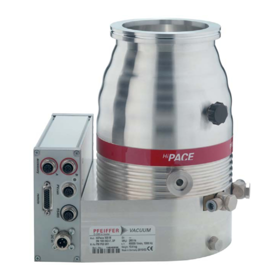
DN 100 ISO-K DN 100 ISO-F DN 100 CF-F Flange material Aluminium Aluminium Stainless steel To correctly identify the product when communicating with Pfeiffer Vacuum, always have the information from the rating plate available. D-35614 Asslar HiPace 300 Oil: Mod.: 260 l/s... -
Page 11: Function
The turbopump HiPace 300 M forms a complete unit together with the electronic drive and magnetic bearing unit TM 700 (in the following just: "electronic drive unit"). For the voltage supply only Pfeiffer Vacuum power supplies may be used (e.g.TPS, OPS or DCU). -
Page 12: Range Of Application
Product description Range of application The pump HiPace 300 M must be installed and operated under the following ambient conditions: Installation location weather protected (indoors) Protection category IP 54 Protection class Ambient temperature +5 °C to +30 °C with convection cooling without gas throughput +5 °C to +35 °C with air cooling +5 °C to +40 °C with water cooling max. -
Page 13: Installation
Only use approved original parts from Pfeiffer Vacuum (Accessories) for the installa- tion. Installation and operation of accessories Pfeiffer Vacuum pumps can be equipped with a series of adapted accessories. The in- stallation, operation and maintenance of connected devices are described in detail in the operating instructions of the individual components. -
Page 14: Use Of A Splinter Shield Or Protection Screen
5.2.2 Use of a splinter shield or protection screen Pfeiffer Vacuum centering rings with splinter shield or protection screen in the high vac- uum flange protect the turbopump against foreign bodies coming from the chamber. Thus, the pumping speed of the pump is reduced. -
Page 15: Mounting Orientation
Installation Mounting orientation When using dry backing pumps, Pfeiffer Vacuum HiPace pumps are designed for instal- lation in any orientation. Support pipes in front of the vacuum pump or remove them. No force from the pipe system may be exerted on the fixed pump. -
Page 16: Connecting The High Vacuum Side
Twisting or tearing-off is possible in case the rotor is suddenly blocked due to the fas- tening of pumps on a vacuum chamber with different flange variants. Use only the correct mounting kit from Pfeiffer Vacuum. Pfeiffer Vacuum will not accept any liability for all damages resulting from impermis- sible fastening. NOTICE... -
Page 17: Installation Of Iso-K Flange With Iso-F Flange
"stud screw and threaded hole," and "stud screw and through hole". For the installation the following components are exclusively authorized: ● the valid mounting kit of the Pfeiffer Vacuum accessories programme ● mounting materials including protection screen or splinter shield are optionally avail-... -
Page 18: Installation Of Iso-F With Iso-F Flange
"stud screw and threaded hole," and "stud screw and through hole". For the installation the following components are exclusively authorized: ● the valid mounting kit of the Pfeiffer Vacuum accessories programme ● mounting materials including protection screen or splinter shield are optionally avail-... -
Page 19: Installation Of Cf- Flanges
The connection types for installation of CF to CF flange are "hexagon screw and through hole", "stud screw and threaded hole" as well as "stud screw and through hole". ● the valid mounting kit of the Pfeiffer Vacuum accessories programme ● A copper seal ●... -
Page 20: Connecting The Fore-Vacuum Side
Installation Connecting the fore-vacuum side Recommendation: As backing pump, use a suitable vacuum pump from the Pfeiffer Vacuum programme. WARNING Damage to health due to poisonous gases Process gases can damage health and contaminate the environment. Safely lead away the gas emission from the backing pump! ... -
Page 21: Connections To The Turbopump
Detailed description for function, configuration and operation with the respective connec- tion panel are given in the specific operating instructions for the electronic drive unit. 5.6.2 Earthing Pfeiffer Vacuum recommends to connect an appropriate earthing wire to derive applica- tive interferences. Fig. 6: Installing the earthing connection 5.6.3... -
Page 22: Accessory Connection
To connect two units to one accessory connection, use the appropriate Y-Connector from the Pfeiffer Vacuum range of accessories. Connect the adapter to the appropriate red-coded connection on the TM 700. Y-Connector ... -
Page 23: Venting Valve
Counter sunk screw Insert the threaded adapter into the designated borehole of the pump lower part. Fix the Pfeiffer Vacuum air cooling unit to the holes of the turbopump and the threaded adapter using two screws. Plug in and fix the accessory’s control lead to the corresponding accessory connection port on the electronic drive unit. -
Page 24: Sealing Gas Connection
Installation 5.7.3 Sealing gas connection The turbopump must be operated with sealing gas to protect it, such as in the case of unclean processes or high gas throughput. The supply is made via a sealing gas valve or alternatively via a sealing gas throttle without control. The activation of the control valve for the sealing gas connection is not pre-installed in the electronic drive unit and has to be configured via their interfaces. - Page 25 Installation CAUTION Risk of burns High temperatures arise when the turbopump or vacuum chamber are baked out. As a result, there is a danger of burns from touching hot parts, even after the casing heating is switched off! Thermally insulate heating jacket, pump housing and vacuum chamber, if possible during installation.
-
Page 26: Water Cooling
Installation 5.7.5 Water cooling The turbopumps HiPace 300 M with TM 700 have water cooling as standard equipment. ● In case of increased backing pressure (> 0.1 hPa) and/or operation with high gas throughputs, either air or water cooling may be used. ●... -
Page 27: Operation
Pumping of gases with a higher molecular mass in the wrong gas mode can lead to de- struction of the pump. Ensure the gas mode is correctly set. Contact Pfeiffer Vacuum before using gases with a greater molecular mass (> 80). 6.1.1 Magnetic bearing calibration In rare cases, the magnetic bearing sensors may trigger re-calibration on enabling of the drive electronics. -
Page 28: Operation Modes
Consider the following manuals for the operation via remote control: ● Operating instructions "Electronic drive unit TM 700" 6.3.2 Operation with DCU or HPU Consider the following manuals for the operation via Pfeiffer Vacuum display and con- trol units: ● Operating instructions "DCU" ● Operating instructions "HPU"... -
Page 29: Switching Off And Venting
The magnetic bearing sensorics permanently monitor the current rotor balance. The bal- ance is expressed as a percentage of the maximum possible rotor imbalance due to the drive electronics and can be viewed via the RS-485 interface using the Pfeiffer Vacuum display and control unit or PC. -
Page 30: Emergency Power Supply
Only vent the pump via the provided venting valve. Do not replace the Pfeiffer Vacuum venting valve by other venting units. It is recommended first to vent via the Pfeiffer Vacuum venting valve until a rotation speed of 6000 rpm, before using additional venting units. -
Page 31: Maintenance / Replacement
Decontaminate affected parts before carrying out maintenance work. NOTICE Disclaimer of liability Pfeiffer Vacuum accepts no liability for personal injury or material damage, losses or op- erating malfunctions due to improperly performed maintenance. The liability and war- ranty entitlement expires. -
Page 32: Magnetic Bearing Calibration
Maintenance / replacement Only separate the pump and the electronic drive unit from each other after disconnect- ing the supply voltage and the complete standstill of the pump. Remove the vacuum pump from the system, if necessary. Unscrew the venting valve control lead from the electronic drive unit. ... -
Page 33: Decommissioning
Check turbopump for contamination and moisture. Clean the turbopump externally with a lint-free cloth and little industrial alcohol. If necessary, have Pfeiffer Vacuum Service clean the turbopump completely. Installation and commissioning in accordance with the operating instructions. -
Page 34: Malfunctions
Reset via pin 13 on the "remote" connection Differentiated malfunction display is possible via "RS 485" Contact the Pfeiffer Vacuum Service If no Pfeiffer Vacuum display and control unit is available, please contact the Pfeiffer Vacuum Service. -
Page 35: 10 Service
The following steps are necessary to ensure a fast, smooth servicing process: Download the forms "Service Request" and "Declaration on Contamination". Fill out the "Service Request" form and send it by fax or e-mail to your Pfeiffer Vacuum service address. -
Page 36: 11 Spare Parts Hipace 300 M
Spare parts HiPace 300 M 11 Spare parts HiPace 300 M Item Designation Size Order number Notes Pieces Order qty. 15.5 Swiveling screw-fitting P 4131 007 E water cooling unit Electronic drive unit TM 700 according to the rating plate depends on the connection panel Venting valve PM Z01 291... -
Page 37: 12 Accessories
Accessories 12 Accessories Designation DN 100 ISO-K DN 100 CF-F DN 100 ISO-F Mounting kit for HiPace 300 M, DN 100 ISO-K, including coated center- PM 016 775 -T ing ring, bracket screws Mounting kit for HiPace 300 M, DN 100 ISO-K, including coated center- PM 016 777 -T ing ring with protective screen, bracket screws Mounting kit for HiPace 300 M, DN 100 ISO-K, including coated center-... - Page 38 Accessories Designation DN 100 ISO-K DN 100 CF-F DN 100 ISO-F Power separator for RS-485 PT 348 132 -T PT 348 132 -T PT 348 132 -T USB converter to RS-485 interface PM 061 207 -T PM 061 207 -T PM 061 207 -T Connector M12 to RS-485 PM 061 270 -X...
-
Page 39: 13 Technical Data And Dimensions
Technical data and dimensions 13 Technical data and dimensions 13.1 General Basic principles for the Technical Data of Pfeiffer Vacuum Turbopumps: Maximum values refer exclusively to the input as a single load. ● Recommendations of PNEUROP committee PN5 ● ISO 21360; 2007: "Vacuum technology - Standard methods for measuring vacuum- pump performance - General description"... - Page 40 Technical data and dimensions ® ® ® Parameter HiPace 300 M HiPace 300 M HiPace 300 M Fore-vacuum max. for N 20 hPa 20 hPa 20 hPa Run-up time < 2 min < 2 min < 2 min Ultimate pressure according to PNEUROP <...
-
Page 41: 13.3 Dimensions
Technical data and dimensions 13.3 Dimensions Ø150 DN 16 ISO-KF / G1/4" DN 100 ISO-K Ø162 G1/8" Ø8 / G1/4" (2x) M8 (6x) Fig. 14: HiPace 300 M, DN 100 ISO-K Ø150 DN 16 ISO-KF / G1/4" DN 100 ISO-F Ø162 G1/8"... -
Page 42: Declaration Of Conformity
● Restriction of the use of certain Hazardous Substances 2011/65/EU The agent responsible for compiling the technical documentation is Mr. Helmut Bern- hardt, Pfeiffer Vacuum GmbH, Berliner Straße 43, 35614 Aßlar. HiPace 300 M Harmonised standards and national standards and specifications which have been ap-... - Page 43 VACUUM SOLUTIONS FROM A SINGLE SOURCE Pfeiffer Vacuum stands for innovative and custom vacuum solutions worldwide, technological perfection, competent advice and reliable service. COMPLETE RANGE OF PRODUCTS From a single component to complex systems: We are the only supplier of vacuum technology that provides a complete product portfolio.
Need help?
Do you have a question about the PM P05 167 and is the answer not in the manual?
Questions and answers