Pfeiffer Vacuum HIPACE 1200 Operating Instructions Manual
Turbopump
Hide thumbs
Also See for HIPACE 1200:
- Operating instructions manual (26 pages) ,
- Operating instructions manual (76 pages)
Table of Contents
Advertisement
Quick Links
Advertisement
Table of Contents

Subscribe to Our Youtube Channel
Related Manuals for Pfeiffer Vacuum HIPACE 1200


Summary of Contents for Pfeiffer Vacuum HIPACE 1200
- Page 1 OPERATING INSTRUCTIONS Translation of the Original HIPACE 1200 Turbopump...
- Page 2 Dear Customer, Thank you for choosing a Pfeiffer Vacuum product. Your new turbopump is designed to support you by its performance, its perfect operation and without interfering your individual application. The name Pfeiffer Vacuum stands for high-quality vacuum technology, a comprehensive and complete range of top-quality products and first-class service.
-
Page 3: Table Of Contents
Limits of use of the product Proper use Foreseeable improper use Personnel qualification 2.7.1 Ensuring personnel qualification 2.7.2 Personnel qualification for maintenance and repair 2.7.3 Advanced training with Pfeiffer Vacuum Product description Identifying the product 3.1.1 Product types 3.1.2 Product features Functional properties 3.2.1 Cooling... - Page 4 Operating modes 6.2.1 Operation without operating unit 6.2.2 Operation via connection "E74" 6.2.3 Operation via multi-function connection "remote" 6.2.4 Operation via Pfeiffer Vacuum display and control unit 6.2.5 Operation via field bus Switching on the turbopump Operation monitoring 6.4.1 Operating mode display via LED 6.4.2 Temperature monitoring...
- Page 5 List of tables Tbl. 1: Abbreviations used in this document Tbl. 2: Permissible ambient conditions Tbl. 3: Product designation of Pfeiffer Vacuum HiPace turbopumps Tbl. 4: Turbopump features Tbl. 5: Delivered drive power depending on the supplied mains voltage Tbl. 6:...
- Page 6 List of figures List of figures Fig. 1: HiPace 1200 design (example: standard version, DN 200 ISO-F | U-version DN 200 ISO-K) Fig. 2: Slinging points for transport of the turbopump in the standard and U versions Fig. 3: Example: Secure against displacement and tipping caused by external vi- brations Fig.
-
Page 7: About This Manual
Keep the manual for future consultation. 1.1 Validity This operating instructions is a customer document of Pfeiffer Vacuum. The operating instructions de- scribe the functions of the named product and provide the most important information for the safe use of the device. The description is written in accordance with the valid directives. The information in this op- erating instructions refers to the product's current development status. -
Page 8: Conventions
Rating plate (example) Rating plates of individual assemblies are located on the D-35614 Asslar lower part of the turbopump or on the relevant attachments. HiPace 1200 Mod. PM P03 910 - - - - - - - - PM 006 336 -T TÜV Rheinland... -
Page 9: Abbreviations
Meaning in this document Alternating current (AC) Corrosive gas version Diameter value (in mm) Display Control Unit (Pfeiffer Vacuum display and control unit). Nominal diameter as size description Emergency Stop Rotation speed value of a vacuum pump (frequency, in rpm or Hz) Handheld Programming Unit. -
Page 10: Tbl. 1: Abbreviations Used In This Document
About this manual Abbreviation Meaning in this document Light emitting diode Earthed conductor (protective earth) [P:xxx] Electronic drive unit control parameters. Printed in bold as a three-digit number in square brackets. Frequently displayed in conjunction with a short description. Example: [P:312] software version remote 26-pole D-Sub connecting socket on the turbopump electronic drive unit width across flats... -
Page 11: Safety
Safety 2 Safety 2.1 General safety information The following 4 risk levels and 1 information level are taken into account in this document. DANGER Immediately pending danger Indicates an immediately pending danger that will result in death or serious injury if not observed. ►... - Page 12 Safety Risks during installation DANGER Danger to life from electric shock Contact with exposed and live elements generate an electric shock. Incorrect connection of the mains supply leads to the risk of live housing parts that can be touched. There is a risk to life. ►...
- Page 13 Safety WARNING Risk of serious injury from oscillating, toppling or falling objects Incorrect handling during the mechanical installation leads to a risk of oscillating, toppling or falling heavy loads. There is a risk of crushing and impacts (e.g. on colliding flange connections). There is a risk of injuries to limbs, up to and including bone fractures and head injuries.
- Page 14 Safety Risks during maintenance, decommissioning and disposal WARNING Danger to life from electric shock during maintenance and service work The device is only completely de-energized when the mains plug has been disconnected and the tur- bopump is at a standstill. There is a danger to life from electric shock when making contact with live components.
- Page 15 Safety WARNING Risk of scalding from suddenly escaping hot cooling water The turbopump water connections are open to both sides. When connecting the cooling water supply, there is a risk of scalding from suddenly escaping, hot cooling water at over pressure. ►...
-
Page 16: Safety Precautions
► Follow the installation instructions for this turbopump. ► Observe the requirements regarding stability and design of the counter flange. ► Use only original accessories or fixing material approved by Pfeiffer Vacuum for the installation. WARNING Risk of injury caused by the turbopump breaking away with the vibration compensator in the event of a malfunction Sudden jamming of the rotor generates high destructive torques in accordance with ISO 27892. -
Page 17: Limits Of Use Of The Product
Safety ► Never put the device into operation with the high vacuum connection open. ► Keep lines and cables away from hot surfaces (> 70°C). ► Never fill or operate the unit with cleaning agents or cleaning agent residues. ► Do not carry out your own conversions or modifications on the unit. ►... -
Page 18: Personnel Qualification
Such training must ensure that individuals are capable of carrying out the required activi- ties and work steps safely and properly. 2.7.2 Personnel qualification for maintenance and repair Advanced training courses Pfeiffer Vacuum offers advanced training courses to maintenance levels 2 and 3. 18/72... -
Page 19: Advanced Training With Pfeiffer Vacuum
─ Customer with Pfeiffer Vacuum service training ─ Pfeiffer Vacuum service technician 2.7.3 Advanced training with Pfeiffer Vacuum For optimal and trouble-free use of this product, Pfeiffer Vacuum offers a comprehensive range of courses and technical trainings. For more information, please contact Pfeiffer Vacuum technical training. -
Page 20: Product Description
ID no. 000021320. 3.1.1 Product types The product designation of Pfeiffer Vacuum turbopumps from the HiPace series is composed of the family name, the size (which is based on the pumping speed of the vacuum pump) and, if required, an additional feature description. -
Page 21: Cooling
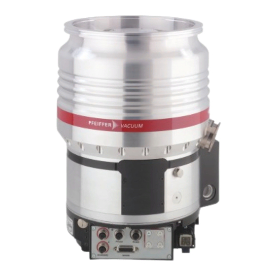
Product description Fig. 1: HiPace 1200 design (example: standard version, DN 200 ISO-F | U-version DN 200 ISO-K) 1 High vacuum connection Protective cover for the high vacuum flange 2 Venting connection, venting screw Protective cap of operating fluid pump 3 Fore-vacuum connection, DN 40 ISO-KF Mains connection "AC in"... -
Page 22: Transportation And Storage
► Drain off the operating fluid before moving or transporting the vacuum pump. ► Only fill the vacuum pump with operating fluid after mechanical installation. Pfeiffer Vacuum recommends keeping the transport packaging and original protective cov- General information regarding safe transport 1. -
Page 23: Storage
– Keep the eye bolts for future use. 4.2 Storage We recommend Pfeiffer Vacuum recommends storing the products in their original transport packaging. Storing the turbopump 1. Seal all flange openings with the original protective caps. 2. Seal all other connections (e.g. venting connection) with the corresponding original parts. -
Page 24: Installation
Installation 5 Installation The installation of the turbopump and its fastening is of outstanding importance. The rotor of the turbo- pump revolves at very high speed. In practice it is not possible to exclude the risk of the rotor touching the stator (e.g. due to the penetration of foreign bodies into the high vacuum connection). The kinetic energy released acts on the housing and on the anchoring of the turbopump within fractions of a sec- ond. -
Page 25: Considering The Earthquake Protection
22.5 W Tbl. 6: Requirements for the dimensioning of customer-specific high vacuum connection Important information for correct installation ► Only use the approved mounting kits of Pfeiffer Vacuum for the high vacuum connection of the turbopump. 5.2.2 Considering the earthquake protection NOTICE... -
Page 26: Using A Splinter Shield Or Protective Screen
5.2.3 Using a splinter shield or protective screen Pfeiffer Vacuum centering rings with splinter shield or protective screen in the high vacuum flange pro- tect the Turbopump against foreign matter from the vacuum chamber. The puming speed of the pump is reduced according to the passage guide values and the size of the high vacuum flange. -
Page 27: Mounting Orientations
Installation 5.2.5 Mounting orientations NOTICE Destruction of the vacuum pump due to failure to observe the type-specific spatial position Impermissible spatial positions lead to pollution of the vacuum pump by operating fluid. There is a risk of pollution of the process vacuum and damage to the vacuum pump up to and including its de- struction. -
Page 28: Attaching Iso-K Flange Onto Iso-K
Flange connection ISO-K to ISO-F, bracket screws Connection with bracket screw 1. For the connection of the turbopump, use only the approved mounting kits from Pfeiffer Vacuum. 2. Connect the flange with the components of the mounting kit according to the figure. -
Page 29: Attaching Iso-F Flange To Iso-F
Connection of the stud screw and tapped hole 1. For the connection of the turbopump, use only the approved mounting kits from Pfeiffer Vacuum. 2. Screw in the required number of stud screws with the shorter end in the holes on the counter flange. -
Page 30: Fig. 11: Flange Connection Iso-F, Hexagon Head Screw And Tapped Hole
Connection of the hexagon head screw and tapped hole 1. For the connection of the turbopump, use only the approved mounting kits from Pfeiffer Vacuum. 2. Attach the turbopump with centering ring to the counter flange according to the figure. -
Page 31: Attaching Cf Flange To Cf-F
Connection of the stud screw and through hole 1. For the connection of the turbopump, use only the approved mounting kits from Pfeiffer Vacuum. 2. Attach the turbopump with collar flange, snap ring and centering ring to the counter flange accord- ing to the figure. -
Page 32: Filling The Operating Fluid
Connection of the stud screw and tapped hole 1. For the connection of the turbopump, use only the approved mounting kits from Pfeiffer Vacuum. 2. Screw in the required number of stud screws with the shorter end in the holes on the counter flange. -
Page 33: Fig. 18: Removing The Protective Cap On U- Or Standard Versions
► Fill the turbopump with operating fluid via one of the filler screws marked with an oil can symbol only. ► If in doubt, contact Pfeiffer Vacuum. The operating fluid pump of the turbopump is situated beneath a protective cap. The screws for filling the operating fluid are identified with a respective symbol. -
Page 34: Connecting The Fore-Vacuum Side
Use the turbopump only in combination with a suitable backing pump that can deliver up to the required maximum fore-vacuum pressure. To achieve the fore-vacuum pressure, use a suitable vacuum pump or a pumping station from the Pfeiffer Vacuum range. In this case, the backing pump is also controlled directly via the turbopump electronic drive unit interfaces (e.g., relay box or connection cable). -
Page 35: Connecting The Cooling Water Supply
► Prior to installation, ensure that pressure is discharged from the cooling water system, and that it is cooled down. ► Wear protective equipment, e.g., safety goggles and gloves. The HiPace 1200 turbopumps use water cooling as standard. 35/72... -
Page 36: Tbl. 8: Requirements On The Cooling Water Composition
4 Threaded nozzle (2x) Procedure Pfeiffer Vacuum recommends the use of a dirt trap in the supply line. 1. Screw one hose nozzle with sealing ring onto each of the turbopump's cooling water connections. – Tightening torque: max. 15 Nm 2. -
Page 37: Connecting Accessories
2. Note the existing configuration of existing connections and control lines. 3. Connect only matching accessory devices to the electronic drive unit. 4. Use the Y-distributor from the Pfeiffer Vacuum range of accessories if you want to connect 3 or 4 devices. -
Page 38: Grounding The Vacuum Pump
Installation 5.7.1 Grounding the vacuum pump Fig. 22: Example: Connecting the grounding cable Required aids ● Screw M4 × 8 ● Shake proof washer M4, if required ● Suitable grounding cable with cable lug size M4 Procedure 1. Use a suitable grounding cable to divert applicative interferences. 2. - Page 39 There are 2 options for configuring the mains connection for the turbopump. ► Make sure that you have the correct supply voltage. ► Order a corresponding mains connection cable from the Pfeiffer Vacuum accessories range. ► Assemble your own mains connection cable using the HAN 3A connecting socket from the ship- ment.
-
Page 40: Operation
Simultaneous loading by means of high drive power (gas throughput, fore-vacuum pressure), high heat radiation, or strong magnetic fields results in uncontrolled heating of the rotor and can destroy the vacuum pump. ► Consult Pfeiffer Vacuum before combining varying loads on the vacuum pump. Lower limit val- ues apply. NOTICE... -
Page 41: Operating Modes
Instructions for operation without control panel 1. Use only the approved Pfeiffer Vacuum mating plug with bridges on the connection of the elec- tronic drive unit. 2. Switch on the mains supply of the turbopump only immediately before operation. -
Page 42: Switching On The Turbopump
6.4.1 Operating mode display via LED LEDs on the electronic drive unit show the basic operating states of the vacuum pump. A differentiated error and warning display is only possible for operation with the Pfeiffer Vacuum display and control unit or a PC. -
Page 43: Temperature Monitoring
Operation Symbol LED status Display Meaning Currentless On, flashing "pumping station OFF", rotation speed ≤ 60 rpm Green On, inverse flashing "pumping station ON", set rotation speed not reached On, constant "pumping station ON", set rotation speed reached On, flashing "pumping station OFF", speed >... -
Page 44: Tbl. 14: Factory Settings For Delayed Venting In Turbopumps
General information for fast venting We recommend fast venting of larger volumes in 4 steps. 1. Use a Pfeiffer Vacuum venting valve for the turbopump, or match the valve cross-section to the size of the recipient and maximum venting rate. -
Page 45: Maintenance
5. Replace the operating fluid at least every 4 years. 6. Have Pfeiffer Vacuum Service replace the rotor bearing of the turbopump at least every 4 years. 7. Consult with Pfeiffer Vacuum Service about shorter maintenance intervals for extreme loads or im- pure processes. -
Page 46: Changing The Operating Fluid
Maintenance 7.3 Changing the operating fluid WARNING Risk of poisoning from contact with harmful substances The operating fluid and parts of the turbopump may contain toxic substances from pumped media. ► Decontaminate affected parts before carrying out maintenance work. ► Prevent health hazards or environmental impacts with adequate safety precautions. ►... -
Page 47: Filling The Operating Fluid
► Only fill the turbopump with operating fluid after mechanical installation. ► Fill the turbopump with operating fluid via one of the filler screws marked with an oil can symbol only. ► If in doubt, contact Pfeiffer Vacuum. Required tools ● Allen key, size 5 ●... -
Page 48: Replacing The Electronic Drive Unit
Maintenance Fig. 25: Position of the operating fluid filler screws depending on orientation of the turbo- pump 1 Filler screw Drain screw 2 O-ring Procedure 1. Unscrew and remove the higher filler screw from the operating fluid pump. 2. Use the syringe and the operating fluid from the turbopump shipment. 3. -
Page 49: Fig. 26: Replacing The Electronic Drive Unit - Removal
Maintenance Backing up settings made by the customer The factory operating parameters are always preset in replacement units. All settings made by the customer to the original electronic drive unit are lost when it is replaced. To preserve your custom settings, you have the following options: 1. -
Page 50: Confirming The Speed Specification
Maintenance Fig. 27: Replacing the electronic drive unit – Installation 1 Electronic drive unit TC 1200 O-ring 2 Connecting plug Cooling plate Installing the electronic drive unit 1. If needed, secure the O-ring in the groove in the pump base. 2. -
Page 51: Tbl. 15: Characteristic Nominal Rotation Speeds Of The Turbopumps
Tbl. 15: Characteristic nominal rotation speeds of the turbopumps Required aids ● A connected Pfeiffer Vacuum display and control unit. ● Knowledge of the configuration and setting of electronic drive unit operating parameters. Adjusting the nominal rotation speed confirmation 1. Observe the display and control unit operating instructions. -
Page 52: Decommissioning
Procedures for recommissioning the turbopump 1. Check the turbopump for pollution and moisture. 2. Clean the turbopump exterior with a lint-free cloth and a little isopropanol. 3. If necessary, arrange for Pfeiffer Vacuum Service to completely clean the turbopump. 52/72... - Page 53 Decommissioning 4. Observe the total running time of the turbopump and if necessary, arrange for Pfeiffer Vac- uum Service to replace the bearing. 5. Change the turbopump's operating fluid. 6. Install the turbopump according to these instructions (see chapter “Installation”, page 24).
-
Page 54: Recycling And Disposal
9.1 General disposal information Pfeiffer Vacuum products contain materials that you must recycle. ► Dispose of our products according to the following: – Iron –... -
Page 55: Malfunctions
► Follow the installation instructions for this turbopump. ► Observe the requirements regarding stability and design of the counter flange. ► Use only original accessories or fixing material approved by Pfeiffer Vacuum for the installation. WARNING Risk of injury caused by the turbopump breaking away with the vibration compensator in the event of a malfunction Sudden jamming of the rotor generates high destructive torques in accordance with ISO 27892. - Page 56 ● Reduce the process gas load. ● Rotor not running ● Check the turbopump for noise development smoothly, defective bear- ● Contact Pfeiffer Vacuum Service. ● Run-up time setpoint ad- ● Extend the run-up time setpoint [P:700] via a dis- justed too low play and control unit.
-
Page 57: Service Solutions By Pfeiffer Vacuum
We are always focused on perfecting our core competence – servicing of vacuum components. Once you have purchased a product from Pfeiffer Vacuum, our service is far from over. This is often exactly where service begins. Obviously, in proven Pfeiffer Vacuum quality. - Page 58 Service solutions by Pfeiffer Vacuum 5. Prepare the product for transport in accordance with the provisions in the contamination declaration. a) Neutralize the product with nitrogen or dry air. b) Seal all openings with blind flanges, so that they are airtight.
-
Page 59: Spare Parts
Spare parts 12 Spare parts Fig. 29: Spare parts HiPace 1200 Position Designation Size order number Note Pieces Quan- tity Electronic drive unit refer to the rating plate depending on the con- TC 1200 nection panel "remote" mating plug PM 061 378 -X... -
Page 60: Accessories
Optionally with splinter shield or protective screen. Power supply packs and display units Power supply packs for optimal voltage supply of Pfeiffer Vacuum products are characterized by their compact size and adapted power supply with maximum reliability. Display and operating units are used to check and adjust operating parameters. - Page 61 Sealing gas valve, shielded, HiPace 400/700/800 P with TC 400 and HiPace PM Z01 313 1200–2300 with TC 1200 Sealing gas throttle for HiPace 400/700/800 P version and HiPace 1200–2300 PM Z01 318 Sealing gas throttle for HiPace 1200–2300 PM Z01 319...
-
Page 62: Tbl. 18: Accessories
Accessories Description Order number Sealing gas throttle for HiPace 1200–2300, 52.5 ± 7.5 sccm PM Z01 325 Relay box, shielded, for backing pumps, 1-phase 7 A for TC 400/1200, TM 700 PM 071 284 -X and TCP 350, M12 Relay box, shielded, for backing pumps, 1-phase 20 A for TC 400/1200, TM 700... -
Page 63: Technical Data And Dimensions
Technical data and dimensions 14 Technical data and dimensions 14.1 General This section describes the basis for the technical data of Pfeiffer Vacuum turbopumps. Technical data Maximum values refer exclusively to the input as a single load. ● Specifications according to PNEUROP committee PN5 ●... - Page 64 5 – 85 %, not condens- Mounting orientation 0° (HV flange top) – 90° 0° (HV flange top) – 90° 0° (HV flange top) – 90° Weight 30 kg 31.9 kg 41 kg Tbl. 21: Technical data for HiPace 1200 Standard 64/72...
- Page 65 Technical data and dimensions Selection field HiPace® 1200 U with HiPace® 1200 U with HiPace® 1200 U with TC 1200, DN 200 ISO- TC 1200, DN 200 ISO-F TC 1200, DN 200 CF-F Order number PM P03 913 PM P03 914 PM P03 915 Flange (in) DN 200 ISO-K...
- Page 66 Weight 30 kg 31.9 kg 41 kg Tbl. 22: Technical data for HiPace 1200 U Selection field HiPace® 1200 C with HiPace® 1200 C with HiPace® 1200 C with TC 1200, DN 200 ISO- TC 1200, DN 200 ISO-...
- Page 67 0° (HV flange top) – 90° Weight 30 kg 31.9 kg 41 kg Tbl. 23: Technical data for HiPace 1200 C Selection field HiPace® 1200 UC with HiPace® 1200 UC with HiPace® 1200 UC with TC 1200, DN 200 ISO-...
-
Page 68: Dimensions
Mounting orientation 90° – 180° (HV flange 90° – 180° (HV flange 90° – 180° (HV flange bottom) bottom) bottom) Weight 30 kg 31.9 kg 41 kg Tbl. 24: Technical data for HiPace 1200 UC 14.3 Dimensions Dimensions in mm 68/72... -
Page 69: Fig. 30: Hipace 1200 | Dn 200 Iso-K
Ø 240 DN 200 ISO-K G 1/4“ G 1/8“ G 1/8“ 141.9 DN 40 ISO-KF Fig. 30: HiPace 1200 | DN 200 ISO-K Ø 285 Ø 264 DN 200 ISO-F G 1/4“ G 1/8“ G 1/8“ 141.9 DN 40 ISO-KF Fig. -
Page 70: Fig. 33: Hipace 1200 U | Dn 200 Iso-K
G 1/4“ G 1/8“ G 1/8“ 141.9 Ø 240 Ø 264 DN 200 ISO-K Fig. 33: HiPace 1200 U | DN 200 ISO-K DN 40 ISO-KF G 1/4“ G 1/8“ G 1/8“ Ø 264 141.9 Ø 285 DN 200 ISO-F Fig. -
Page 71: Declaration Of Conformity
DIN EN 61010-1: 2011 DIN EN 61326-1: 2013 DIN EN 62061: 2013 The authorized representative for the compilation of technical documents is Mr. Tobias Stoll, Pfeiffer Vacuum GmbH, Berliner Straße 43, 35614 Asslar, Germany. Signature: Pfeiffer Vacuum GmbH Berliner Straße 43...
Need help?
Do you have a question about the HIPACE 1200 and is the answer not in the manual?
Questions and answers