Pfeiffer Vacuum HIPACE 80 Operating Instructions Manual
Turbopump
Hide thumbs
Also See for HIPACE 80:
- Operating instructions manual (44 pages) ,
- Operating instructions manual (10 pages) ,
- Operating instructions manual (26 pages)
Table of Contents
Advertisement
Advertisement
Table of Contents

Related Manuals for Pfeiffer Vacuum HIPACE 80


Summary of Contents for Pfeiffer Vacuum HIPACE 80
- Page 1 OPERATING INSTRUCTIONS Translation of the Original HIPACE 80 Turbopump...
- Page 2 Dear Customer, Thank you for choosing a Pfeiffer Vacuum product. Your new turbopump is designed to support you by its performance, its perfect operation and without interfering your individual application. The name Pfeiffer Vacuum stands for high-quality vacuum technology, a comprehensive and complete range of top-quality products and first-class service.
-
Page 3: Table Of Contents
Limits of use of the product Proper use Foreseeable improper use Personnel qualification 2.7.1 Ensuring personnel qualification 2.7.2 Personnel qualification for maintenance and repair 2.7.3 Advanced training with Pfeiffer Vacuum Product description Function 3.1.1 Cooling 3.1.2 Rotor bearing 3.1.3 Drive... - Page 4 Commissioning Operating modes 6.2.1 Operation without operating unit 6.2.2 Operation via multi-function connection "X3" 6.2.3 Operation via Pfeiffer Vacuum display and control unit 6.2.4 Operation via field bus Switching on the turbopump Operation monitoring 6.4.1 Operating mode display via LED 6.4.2 Temperature monitoring...
- Page 5 Factory settings for delayed venting in turbopumps Tbl. 10: Characteristic nominal rotation speeds of the turbopumps Tbl. 11: Troubleshooting turbopumps Tbl. 12: Overview of the spare parts available for the HiPace 80 Tbl. 13: Accessories Tbl. 14: Conversion table: Pressure units Tbl. 15: Conversion table: Units for gas throughput Tbl.
- Page 6 Flange connection CF-F, stud screw and tapped hole Fig. 10: Flange connection CF-F, stud screw and through hole Fig. 11: Example of fore-vacuum connection on HiPace 80 Fig. 12: Example of accessory connection via adapter TCS 12 Fig. 13: Example: Connecting the grounding cable Fig.
-
Page 7: About This Manual
Keep the manual for future consultation. 1.1 Validity These operating instructions are for customers of Pfeiffer Vacuum. They describe the function of the designated product and provide the most important information for safe usage of the product. The de- scriptions comply with applicable directives. All information provided in these operating instructions refer to the current development status of the product. -
Page 8: Pictographs
This section describes all the stickers on the product along with their meaning. Rating plate The rating plate of the turbopump is located on the lower part D-35614 Asslar HiPace 80 of the vacuum pump. Mod. PM P03 940 Rating plate of the electronic drive unit... -
Page 9: Abbreviations
About this manual 1.3.4 Abbreviations Abbreviation Meaning in this document Flange: Metal-sealed connector in accordance with ISO 3669 Diameter value (in mm) Direct current Display Control Unit. Nominal diameter as size description Rotation speed value of a vacuum pump (frequency, in rpm or Hz) Handheld Programming Unit. -
Page 10: Safety
Safety 2 Safety 2.1 General safety instructions This document includes the following 4 risk levels and 1 information level. DANGER Imminent danger Indicates a hazardous situation which, if not avoided, will result in death or serious injury. ► Instructions on avoiding the hazardous situation WARNING Possibly imminent danger Indicates a hazardous situation which, if not avoided, could result in death or serious injury. - Page 11 ► Take suitable safety precautions on-site for the compensation of the occurring torques. ► Before installing a vibration compensator, you must first of all contact Pfeiffer Vacuum. WARNING Danger to life from poisoning where toxic process media leak from damaged connections Sudden twisting of the turbopump in the event of a fault causes fittings to accelerate.
- Page 12 Safety WARNING Risk of injury due to incorrect installation Dangerous situations may arise from unsafe or incorrect installation. ► Do not carry out your own conversions or modifications on the unit. ► Ensure the integration into an Emergency Off safety circuit. WARNING Danger of cut injuries from unexpected start up.
- Page 13 ► Follow the installation instructions for this turbopump. ► Observe the requirements regarding stability and design of the counter flange. ► Use only original accessories or fixing material approved by Pfeiffer Vacuum for the installation. WARNING Risk of injury caused by the turbopump breaking away with the vibration compensator in the event of a malfunction Sudden jamming of the rotor generates high destructive torques in accordance with ISO 27892.
-
Page 14: Safety Precautions
Safety WARNING Danger to life from poisoning where toxic process media leak from damaged connections Sudden twisting of the turbopump in the event of a fault causes fittings to accelerate. There is the risk of damaging on-site connections (e.g., fore-vacuum line) and resulting leaks. This results in leakage of process media. -
Page 15: Proper Use
● Use of accessories or spare parts that are not listed in these instructions 2.7 Personnel qualification The work described in this document may only be carried out by persons who have appropriate profes- sional qualifications and the necessary experience or who have completed the necessary training as provided by Pfeiffer Vacuum. 15/56... -
Page 16: Ensuring Personnel Qualification
─ Customer with Pfeiffer Vacuum service training ─ Pfeiffer Vacuum service technician 2.7.3 Advanced training with Pfeiffer Vacuum For optimal and trouble-free use of this product, Pfeiffer Vacuum offers a comprehensive range of courses and technical trainings. For more information, please contact Pfeiffer Vacuum technical training. -
Page 17: Product Description
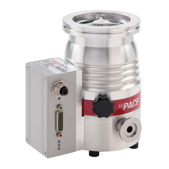
Product description 3 Product description 3.1 Function The turbopump forms a compact unit with the electronic drive unit. Pfeiffer Vacuum power supply packs provide the voltage supply. Fig. 3: HiPace 80 design 1 Protective cover for the high vacuum connec- Electronic drive unit TC 110... -
Page 18: Scope Of Delivery
ID no. 000021320. 3.3.1 Product types The product designation of Pfeiffer Vacuum turbopumps from the HiPace series is composed of the family name, the size (which is based on the pumping speed of the vacuum pump) and, if required, an additional feature description. -
Page 19: Transportation And Storage
► Do not stack the products. ► Wear protective equipment, e.g. safety shoes. We recommend Pfeiffer Vacuum recommends keeping the transport packaging and original protective cov- Instructions for safe transport ► Transport the turbopump only within the permissible temperature limits. -
Page 20: Installation
Installation 5 Installation The installation of the turbopump and its fastening is of outstanding importance. The rotor of the turbo- pump revolves at very high speed. In practice it is not possible to exclude the risk of the rotor touching the stator (e.g. due to the penetration of foreign bodies into the high vacuum connection). The kinetic energy released acts on the housing and on the anchoring of the turbopump within fractions of a sec- ond. -
Page 21: Considering Earthquake Protection
90 °C Tbl. 5: Requirements for the dimensioning of customer-specific high vacuum connection Important information for correct installation ► Only use the approved mounting kits of Pfeiffer Vacuum for the high vacuum connection of the turbopump. 5.2.2 Considering earthquake protection NOTICE... -
Page 22: Using A Splinter Shield Or Protective Screen
Safety connections, customer-side 5.2.3 Using a splinter shield or protective screen Pfeiffer Vacuum centering rings with splinter shield or protective screen in the high vacuum flange pro- tect the turbopump against foreign matter from the vacuum chamber. The pumping speed of the turbo- pump reduces according to the passage guide values and the size of the high vacuum flange. -
Page 23: Mounting Orientations
4. Observe the fastening of the ISO flanges. 5.2.5 Mounting orientations Pfeiffer Vacuum turbopumps from the HiPace series are suitable for use with dry compressing backing pumps for mounting in all orientations. ► When using oil-sealed backing pumps, avoid backflow from the fore-vacuum range. -
Page 24: Attaching Iso-K Flange Onto Iso-K
Flange connection ISO-K to ISO-F, bracket screws Connection with bracket screw 1. For the connection of the turbopump, use only the approved mounting kits from Pfeiffer Vacuum. 2. Connect the flange with the components of the mounting kit according to the figure. -
Page 25: Attaching Cf Flange To Cf-F
Installation Connection of hexagon head set screw and tapped hole 1. Only use the approved mounting kits from Pfeiffer Vacuum for the connection. 2. Place the collar flange over the high vacuum flange on the turbopump. 3. Insert the snap ring into the side groove on the high vacuum flange of the turbopump. -
Page 26: Fig. 8: Flange Connection Cf-F, Hexagon Head Screw And Through Hole
Connection of the hexagon head screw and through holes 1. For the connection of the turbopump, use only the approved mounting kits from Pfeiffer Vacuum. 2. If used: Insert the protective screen or splinter shield with clamping lugs downwards in the turbo- pump high vacuum flange. -
Page 27: Connecting The Fore-Vacuum Side
Connection of the stud screw and through hole 1. For the connection of the turbopump, use only the approved mounting kits from Pfeiffer Vacuum. 2. If used: Insert the protective screen or splinter shield with clamping lugs downwards in the turbo- pump high vacuum flange. -
Page 28: Connecting Accessories
► Observe the installation instructions in the operating instructions for the relevant accessory. ► Note the existing configuration of existing connections and control lines. ► Use the Pfeiffer Vacuum display and control unit DCU 002, or a DCU with integrated power supply pack. -
Page 29: Connecting The Electrical Supply
► Do not carry out your own conversions or modifications on the unit. ► Ensure the integration into an Emergency Off safety circuit. 5.5.1 Earthing the turbopump Pfeiffer Vacuum recommends connecting a suitable grounding cable to discharge applicative interfer- ences. Fig. 13:... -
Page 30: Fig. 14: Connecting The Electronic Drive Unit To A Power Supply Pack
Installation WARNING Danger of cut injuries from unexpected start up. The use of mating plugs of the electronic drive unit (accessories) enables the automatic run-up of the vacuum pump as soon the power is turned on. Attaching mating plugs before or during the installa- tion leads to the movement of parts hence the risk of cut injuries by sharp-edged in the exposed high vacuum flange. -
Page 31: Operation
Simultaneous loading by means of high drive power (gas throughput, fore-vacuum pressure), high heat radiation, or strong magnetic fields results in uncontrolled heating of the rotor and can destroy the vacuum pump. ► Consult Pfeiffer Vacuum before combining varying loads on the vacuum pump. Lower limit val- ues apply. NOTICE... -
Page 32: Operating Modes
"with bridges" and running the supply voltage. Notes on operation without control unit 1. Only use the approved Pfeiffer Vacuum connection cables with bridges on the "X3" connection on the electronic drive unit. -
Page 33: Switching On The Turbopump
6.4.1 Operating mode display via LED LEDs on the electronic drive unit show the basic operating states of the vacuum pump. A differentiated error and warning display is only possible for operation with the Pfeiffer Vacuum display and control unit or a PC. -
Page 34: Temperature Monitoring
This causes mechanical damage to the turbopump, including potential failure. ► Observe the prescribed maximum pressure rise speed of 15 hPa/s. ► Avoid manual and uncontrolled venting of very low volumes. ► Where necessary, use a venting valve from the Pfeiffer Vacuum range of accessories. 34/56... -
Page 35: Tbl. 9: Factory Settings For Delayed Venting In Turbopumps
General information for fast venting We recommend fast venting of larger volumes in 4 steps. 1. Use a Pfeiffer Vacuum venting valve for the turbopump, or match the valve cross-section to the size of the recipient and maximum venting rate. -
Page 36: Maintenance
5. Change the operating fluid reservoir at least every 4 years. 6. Have Pfeiffer Vacuum Service replace the rotor bearing of the turbopump at least every 4 years. 7. Consult with Pfeiffer Vacuum Service about shorter maintenance intervals for extreme loads or im- pure processes. -
Page 37: Replacing The Operating Fluid Reservoir
► Never use sharp, metallic tools (e.g., tweezers). ► Only remove sealing rings with an O-ring picker. You can find the safety data sheet in the Pfeiffer Vacuum Download Center. Prerequisites ● Turbopump switched off ● Vacuum system vented to atmospheric pressure ●... -
Page 38: Installing The Operating Fluid Reservoir
Maintenance Fig. 15: Removing the operating fluid reservoir 1 Rubber-metal bumper O-ring, operating fluid reservoir 2 Special tool Operating fluid reservoir 3 Wrench Capillary rod (8×) 4 Screw cap Protective cover 5 O-ring Removing the operating fluid reservoir 1. Wear laboratory gloves to avoid skin contact. 2. -
Page 39: Replacing The Electronic Drive Unit
Maintenance Fig. 16: Installing the operating fluid reservoir 1 Screw cap Rubber-metal bumper 2 O-ring Torque wrench 3 O-ring, operating fluid reservoir Special tool 4 Operating fluid reservoir Protective cover 5 Capillary rod (8×) Installing the operating fluid reservoir 1. Insert all new capillary rods with the tweezers. 2. -
Page 40: Confirming The Rotation Speed Specification
Maintenance Backing up settings made by the customer The factory operating parameters are always preset in replacement units. All settings made by the customer to the original electronic drive unit are lost when it is replaced. To preserve your custom settings, you have the following options: 1. -
Page 41: Tbl. 10: Characteristic Nominal Rotation Speeds Of The Turbopumps
4. Open and edit the parameter [P:777]. 5. Set the parameter [P:777] to the required value of the nominal rotation speed in Hertz. Alternative: A Pfeiffer Vacuum SpeedConfigurator for the one-time immediate setting of parameter [P:777] is included with the replacement units. -
Page 42: Decommissioning
2. Clean the turbopump externally with a lint-free cloth and a little isopropanol. 3. If necessary, arrange for Pfeiffer Vacuum Service to completely clean the turbopump. 4. Observe the total running time of the turbopump and if necessary, arrange for Pfeiffer Vac- uum Service to replace the bearing. -
Page 43: Disposing Of The Vacuum Pump
Decommissioning 8.3 Disposing of the vacuum pump WARNING Health hazard through poisoning from toxic contaminated components or devices Toxic process media result in contamination of devices or parts of them. During maintenance work, there is a risk to health from contact with these poisonous substances. Illegal disposal of toxic sub- stances causes environmental damage. -
Page 44: Malfunctions
► Follow the installation instructions for this turbopump. ► Observe the requirements regarding stability and design of the counter flange. ► Use only original accessories or fixing material approved by Pfeiffer Vacuum for the installation. WARNING Risk of injury caused by the turbopump breaking away with the vibration compensator in the event of a malfunction Sudden jamming of the rotor generates high destructive torques in accordance with ISO 27892. -
Page 45: Tbl. 11: Troubleshooting Turbopumps
● Reduce the process gas load. ● Rotor not running ● Check the turbopump for noise development smoothly, defective ● Contact Pfeiffer Vacuum Service. bearing ● Run-up time setpoint ● Extend the run-up time setpoint [P:700] via a dis- adjusted too low play and control unit. -
Page 46: Service Solutions From Pfeiffer Vacuum
We are consistently striving to perfect our core competence, service for vacuum components. And our service is far from over once you’ve purchased a product from Pfeiffer Vacuum. It often enough really just begins then. In proven Pfeiffer Vacuum quality, of course. - Page 47 Service solutions from Pfeiffer Vacuum 5. Prepare the product for transport in accordance with the details in the declaration of contamination. a) Neutralize the product with nitrogen or dry air. b) Close all openings with airtight blank flanges. c) Seal the product in appropriate protective film.
-
Page 48: Spare Parts Hipace
Operating fluid reservoir PM 143 740 -T incl. capillary rods and O-rings Rubber-metal bumper P 3695 700 ZD Tbl. 12: Overview of the spare parts available for the HiPace 80 48/56... -
Page 49: Accessories
Optionally with splinter shield or protective screen. Power supply packs and display units Power supply packs for optimal voltage supply of Pfeiffer Vacuum products are characterized by their compact size and adapted power supply with maximum reliability. Display and operating units are used to check and adjust operating parameters. -
Page 50: Tbl. 13: Accessories
Air cooling for HiPace 60 P, HiPace 80 and SplitFlow 50/80 with TC 110/120 PM Z01 300 Water cooling for HiPace 60 P | HiPace 80 and for SplitFlow 50/80 with push-in fit- PM 016 623 -T ting, 8 mm... -
Page 51: Technical Data And Dimensions
Technical data and dimensions 13 Technical data and dimensions 13.1 General This section describes the basis for the technical data of Pfeiffer Vacuum turbopumps. Technical data Maximum values refer exclusively to the input as a single load. ● Specifications according to PNEUROP committee PN5 ●... - Page 52 Technical data and dimensions Classification advanced HiPace® 80 with HiPace® 80 with HiPace® 80 with TC 110 TC 110 TC 110 Compression ratio for He 1.3 · 10 1.3 · 10 1.3 · 10 Compression ratio for N > 1 · 10 >...
-
Page 53: Dimensions
-25 – 55 °C ture Weight 2.4 kg 3.8 kg 2.4 kg Tbl. 16: Technical data for HiPace 80 | 24 V 13.3 Dimensions Dimensions in mm DN 63 ISO-K 89.3 M5 - 10 deep (6x) 37.5 DN 16 ISO-KF / 1/4“... -
Page 54: Fig. 21: Dimensions Hipace 80 | Dn 40 Iso-Kf
Technical data and dimensions 89.3 DN 40 ISO-KF M5 - 10 deep (6x) 37.5 DN 16 ISO-KF / 1/4“ Fig. 21: Dimensions HiPace 80 | DN 40 ISO-KF 54/56... -
Page 55: Declaration Of Conformity
● Electromagnetic compatibility 2014/30/EU ● Restriction of the use of certain hazardous substances 2011/65/EU The authorized representative for the compilation of technical documents is Mr. Hel- mut Bernhardt, Pfeiffer Vacuum GmbH, Berliner Straße 43, 35614 Asslar, Germany. Turbopump HiPace 80...
Need help?
Do you have a question about the HIPACE 80 and is the answer not in the manual?
Questions and answers