Table of Contents
Advertisement
Quick Links
U
U
P
a
r
t
N
u
m
P
a
r
t
N
u
m
C
a
t
a
l
o
g
n
C
a
t
a
l
o
g
n
S
e
r
i
a
l
n
u
m
S
e
r
i
a
l
n
u
m
ORIGINAL INSTRUCTIONS
s
e
a
n
d
m
s
e
a
n
d
m
b
e
r
b
e
r
u
m
b
e
r
u
m
b
e
r
b
e
r
b
e
r
37050 Vago di Lavagno (VR) – ITALIA -
Tel. +39 045 8989111 Fax +39 045 8989160
a
i
n
t
e
n
a
n
c
a
i
n
t
e
n
a
n
c
UTF2-08-1004-1885315
UTF2-08-1004-1885315
Via dell'Artigianato 1
www.cascorp.com
UTF
e
m
a
n
u
a
l
e
m
a
n
u
a
l
Advertisement
Table of Contents

Related Manuals for Cascade UTF2-08-1004-1885315


Summary of Contents for Cascade UTF2-08-1004-1885315
- Page 1 UTF2-08-1004-1885315 UTF2-08-1004-1885315 ORIGINAL INSTRUCTIONS Via dell’Artigianato 1 37050 Vago di Lavagno (VR) – ITALIA - Tel. +39 045 8989111 Fax +39 045 8989160 www.cascorp.com...
-
Page 2: Table Of Contents
INDEX introduCTION............................. 3 PREMISE ................................3 1.1.1 TYPOGRAPHICAL CONVENTIONS ......................3 APPLIANCES CLAMP ..........................4 PRODUCT PURPOSE ............................4 2.1.1 MANUFACTURER’S INTENDED USE ......................4 2.1.2 IMPROPER AND FORBIDDEN USE ......................4 ... -
Page 3: Introduction
No part of this document may be copied, reproduced or transmitted in any way using any electronic, mechanical or photographic means without express permission to do so from CASCADE ITALIA S.r.l. The equipment by Cascade Italia S.r.l. described in this manual has been built in according with Machinery Directives 2006/42/CE. -
Page 4: Appliances Clamp
2 APPLIANCES CLAMP Product purpose 2.1.1 Manufacturer’s intended use The purpose of horizontal gripping devices is to The horizontal camping device for appliances has grip, handle, unload and stock boxed material. been designed and manufactured to consent the handling of loads that are not pallet-mounted. The Such devices may feature incorporated or semi- arms have... -
Page 5: Technical Features
2.1.3 Technical features Manoeuvring the truck when the load is not in line with the forklift truck’s centre line; The device’s technical features can be deduced from the model code printed on the EC plate. Device type UEA – device with pivoting arms UTB –... -
Page 6: Nameplate Legend
2.2 Nameplate Legend... -
Page 8: Map Of Device Sets
3 MAP OF DEVICE SETS 3.1.1 Main groups Fig. 2.2.1 Map of main groups Description Ref. Q.ty Descrizione CODICI / CODES Cilindro Cylinder assy 6566052 Cilindro Cylinder assy 6552412 Gruppo Protezione Bumper 6583521 Ganascia sinistra Arm subassembly left 6583490 Ganascia destra Arm subassembly right 6583512 Impianto oleodinamico... -
Page 9: Frame Group
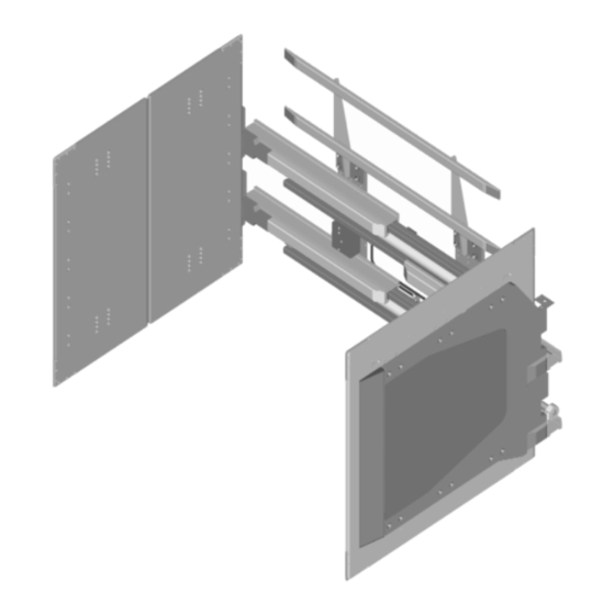
3.1.2 Frame group Fig. 2.3.2 Map of frame group 6522766 BESCHREIBUNG N° CODE ANZ. CAPSCREW M6x16 6400227 CAPSCREW M14x70 6405055 WASHER 6406255 BEARING 6432009 BLOCK SLIDER 6432033 6504163 MOUNTING PLATE 6506606 MOUNTING PLATE 6506607 GUIDE BAR DUAL 6504121 SPACER 6540046... -
Page 10: Mount Group
Mount Group 3.1.3... -
Page 11: Hydraulic System Set
2.3.3 Hydraulic system set Description Codes Hydraulic system set 6563775... - Page 12 ITEM N° PART N° DESCRIPTION 6563775 HYDRAULIC GROUP 6400135 LOCKWASHER 6400136 LOCKWASHER 6405508 CAPSCREW SOCKET HEAD 6405872 CAPSCREW HEX SOCKET 6033791 FITTING 6408611 FITTING 6409504 VALVE RELIEF CARTRIDGE 6429691 TUBE ANCHOR GROUP 6429708 HOSE CLAMP 6506017 VALVE SUPPORT 6521635 BRACKET 6540605 CABLE DRAG CHAIN 6533441...
-
Page 13: Hydraulic Valve 6533441
3.1.6 Hydraulic valve 6533441 ITEM PART N° DESCRIPTION 6533441 VALVE GROUP Contact Cascade VALVE PLUGGED 778100 FITTING M16 FLARELESS 609234 PLUG-HEX SCKT 609455 PLUG HEX SOCKET HD 604510 PLUG 6038929 CART VALVE - PO CHECK 6056395 RELIEF CARTRIDGE DIF/SET 210266... - Page 14 Hydraulic Circuit – External Sideshift Equipped Clamp Cylinders Sideshift Cylinders Attachment Valve One Truck Auxiliary Valve (Solenoid Equipped) Two Truck Auxiliary Valves 1 2 3 4 Solenoid 2-Port Hose Reel 2-Port Hose Reel Internal Reeving Internal Reeving CLAMP (OR FORK POSITION) and SIDESHIFT Truck Auxiliary Valve Truck Relief...
-
Page 15: Arm Group
rm Subassembly RH - LH ARM GROUP 6583512 - 6583490 Rif. Anz. Description CODICE / CODE CAPSCREW 6400227 BEARING 6432009 LOCKING PLATE 6431458 WASHER 6494502 6495524 6504163 ARM BONDED LH 6583508 ARM BONDED RH 6583516 INTERMEDIATE ARM RIGHT 6560452 INTERMEDIATE ARM LEFT 6560424... -
Page 16: Backrest Group
Backrest Group ITEM PART N° DESCRIPTION FITTING 6242855... -
Page 17: General Safety Regulations
4 GENERAL SAFETY REGULATIONS THE SAFETY INDICATIONS INCLUDED IN position possible, or however in a position that is THIS MANUAL AND ON THE MACHINE globally narrower than the device’s frame. ITSELF MUST BE OBSERVED. DO NOT It is forbidden to stop or turn the truck on ramps. TAMPER WITH SAFETY DEVICES AND USE ... -
Page 18: Safety Plates And Pictograms
4.1 Safety plates The horizontal gripping device is fitted with the pictogram shown below, which bears the main safety warnings and precautions that pictograms should be observed for machine use. Read the warnings and instructions for use carefully before using the machine or performing maintenance operations. -
Page 19: Operative Instructions
Cascade Italia recommends that the following hydraulic capacities and working pressures be observed in order to optimise device functioning and to avoid problems during operation or start-up. - Page 20 Pressure losses of tubes with hydraulic oil with a viscosity of 20 cSt at regime temperature (system warm) and of 100 cSt during start-up from cold. The assumption of viscosity is obviously arbitrary, but similar to real conditions. The table below gives the pressure loss values (Bar) per linear meter of tube. ø1/4 G - ø...
-
Page 21: Installation
Installation to remove wrapping Before proceeding with device installation it is to remove the device’s lower brackets necessary: ATTENTION: all loading and manoeuvring operations made using the truck must be performed central to the centre of gravity on the fork, compared to its dimension and weight distribution. - Page 22 Assemble the device on the forklift truck’s plate by handling it with the tilting of the upright in order that the fork holder plate’s upper cone hooks up with the device (see detailed figure). Line up the device’s central retainer (06) with the central niche of the forkholder plate. Reposition the lower brackets (n°05) and tighten the screws with the torque wrench setting as shown in point 5.6.
-
Page 23: Hydraulic Connection
5.3.1 Hydraulic connection Switch off the voltage to the lift truck and perform a few movements of the distributor levers in order to drain the oil from the truck’s system. In order to connect the device to the truck’s hydraulic circuit, it is necessary to: 1. -
Page 24: Maintenance
To remove material.. ATTENTION: any alteration or modification made to the UTB that has not been authorised by Cascade Italia in writing, will cause the invalidation of the EC mark and product guarantee. Do not wash the UTB using jets of water at high pressure. -
Page 25: Bolt Torque Wrench Setting
6.6 Bolt torque wrench setting 10.9 12.9 Rh pitch (mm) (mm²) M (N*m) M (N*m) M (N*m) 1,25 36,6 1,75 84,3 Sliders 6.7.1 Greasing The guides are pre-lubricated in the production phase Greasing the sliders is a routine operation and therefore do not require lubrication when the that must be performed in order to guarantee device is installed for the first time. -
Page 26: Replacing The Sliders
Pull the cylinder rod off completely. GHIERA Replace worn sliders with original Cascade Italia spares. O SNODO Clean and grease the internal surface of the sliders with a brush. -
Page 27: Replacing And Dismantling The Opening And Closing Cylinders
Replacing dismantling opening and closing cylinders Remove the device’s lower brackets (n°14), Remove both arms as described above. hook the ropes up to the device’s frame and Close the cylinders completely dismantle the truck plate. For convenience, ... - Page 28 Slide the cylinders off the device’s frame Reassemble the device on the forkholder and replace with new cylinders as shown on plate of the truck as described in 4.2.3. the spares diagram (see point 2.3.1). Replace the arms as described in 5.4. ...
- Page 29 Rod seal 6521345 Piston wear ring Piston 6402629 Retainer 6402610 Rod wiper 6521341 O ring 6406906 Rod seal 6407005 O ring 70 duro 6406652 Backup ring 6402648 Piston seal 6402628 *SEAL KIT 6527400 Cascade Italia supply only complete Seal kit.
- Page 30 O ring 70 duro 643373 Rod seal 6521345 Piston wear ring Piston 6402629 Retainer 6402610 Rod wiper 6521341 O ring 6406906 O ring 70 duro 6406652 Backup ring 6402648 Piston seal 6402628 *SEAL KIT 6527400 Cascade Italia supply only complete Seal kit.
- Page 31 During cylinder assembly, apply a thin layer (on 10mm of thread for rod diameters less than 55 mm, 20 mm for diameters from 50 – 80 mm and on whole thread for diameters greater than 80 mm) of strong thread- ...
- Page 32 6.8.1 Grease lubrication The table below defines the products to be used to lubricate the various device components. Type of coupling Type of product to be used at room temperature Sliding of arm sliders on sliding SHELL SUPER GREASE AM rail or equivalent lithium based grease with an NLGI 2 consistency.
-
Page 33: Troubleshooting
TROUBLESHOOTING PROBLEMS CAUSE SOLUTION Clamp not synchronised 1.1 Truck capacity out of valve Measure the capacity of the forklift truck and if necessary capacity range. make it be within the field of capacities foreseen for device functioning. 1.2 There is mechanical friction on Carefully lubricate guides. -
Page 34: Ec Declaration Form (Fac-Simile)
EC DECLARATION FORM (FAC-SIMILE)
Need help?
Do you have a question about the UTF2-08-1004-1885315 and is the answer not in the manual?
Questions and answers