Page 1
NSTALLATION INSTRUCTIONS and PERIODIC MAINTENANCE
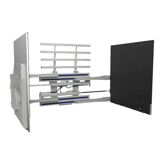
 J-Series Carton Clamps, White Goods Clamps and Tipping Carton Clamps Manual Number 6871082-R2 cascade corporation Cascade is a Registered Trademark of Cascade Corporation...
RECOMMENDED HYDRAULIC SUPPLY J-Series Clamps provide the best performance with one of the hydraulic supply arrangements shown below. Refer to Cascade Hose & Cable Reel Selection Guide, Part No. 212199, to select the correct hose reel for the mast and truck. The hose and fitting requirements are: •...
(19 L/min.) (45 L/min.) (61 L/min.) ➀ Cascade J-Series Carton Clamps are compatible with SAE 10W petroleum base hydraulic fluid meeting Mil. Spec. MIL-0-5606 or MIL-0-2104B. Use of synthetic or aqueous base hydraulic fluid is not recommended. If fire resistant hydraulic fluid is required, GA0380.eps...
MIL-0-5606 or MIL-0-2104B. Use of synthetic or aqueous base hydraulic fluid is not recommended. If fire resistant hydraulic GA0380.eps fluid is required, special seals must be used. Contact Cascade. ➁ Flow less than recommended will result in reduced system performance.
Follow the steps shown to install the attachment on the truck. Read and understand all WARNING and CAUTION statements. If a procedure is not understood, ask a supervisor or call the nearest Cascade Service Department for assistance. Attach overhead hoist WARNING: Verify that the overhead hoist and chains or straps are rated for Remove banding.
Page 6
INSTALLATION Prepare Hoses IMPORTANT: Valve options include LH or RH supply porting for Clamp/Open and Sideshift Left/Right. External sideshifter has top center location porting Determine hose lengths required for hydraulic supply configuration of truck. suitable for both LH or RH supply connections. Cut hoses to length and install end fittings, or use hose kits supplied.
Page 7
INSTALLATION Flush hydraulic supply hoses Install hoses using union fittings. Operate auxiliary valves for 30 seconds. Remove union fittings. Mount attachment on truck carriage Center truck behind the attachment. Tilt forward and raise carriage into position. Engage upper mounting hooks with upper carriage bar.
Page 8
INSTALLATION Install and engage lower hooks BOLT-ON TYPE BOLT-ON TYPE w/ EXTERNAL w/ INTERNAL QUICK-CHANGE TYPE SIDESHIFTING SIDESHIFTING Inspect hooks for IMPORTANT: Adjust Lower excessive clearance. lower hooks for Carriage (Reverse guides to change operating clearance. Lower clearance – See Step 2.) Carriage Tap tight into position.
Page 9
INSTALLATION Install solenoid control knob or push button switch (solenoid-equipped) IMPORTANT: Avoid interference with other control levers and control surfaces. NOTE: Secure the cable so it will not be pinched when the handle is actuated. Snap Ring ID Plate Push Button Switch PRESS BUTTON SIDESHIFT...
Page 10
INSTALLATION Cycle attachment functions WARNING: Truck control handle and • With no load, cycle CLAMP function, SIDESHIFT attachment function activation shown here function and TIPPING function several times. conforms to ANSI/ITSDF B56.1 (ISO 3691) Check for equal arm movement and adequate arm recommended practices.
Page 11
A–E to obtain a desired pressure setting. Pressure CLAMP is not to exceed the maximum pressure setting on the Relief attachment nameplate. If multiple pressure settings are Cartridge desired, contact Cascade for options. CLAMP Supply CLAMP Supply CLAMP Relief CC0040.eps...
Page 12
INSTALLATION Adjust Relief Cartridges (continued) Clamp Relief Adjustment – Clamp Force Method A Cascade 4-Point Force Distribution Tester is required for this procedure. Extend the arms to the most common load width. Lower the contact pads to just above the floor.
Page 13
INSTALLATION CONTACT PAD EXTENSION Attachments supplied with contact pad extensions are installed as follows: Install pivot block to contact pad. Tighten capscrews to 66 ft.-lbs. (90 Nm). Release lever on pivot block. Position the lever to the front face of the pivot block. Insert the lower lock plate into the pad extension.
Check for bent pressure pads, straighten or replace Add or increase CL2504.eps positive camber (Contact Cascade Service) Check for worn lower surfaces, rotate pads 180 ° Re-clamp load and exchange so bottom edge sides or replace...
Page 15
CL2505.eps Re-clamp load Add or increase negative camber so bottom edge (Contact Cascade is even with Service) bottom of pads TYPICAL PAD CAMBER FOR HANDLING CARTON CASE LOADS CANNED / BOTTLED / DENSE CASE GOODS Neutral to positive...
This procedure can be performed with the attachment mounted on the truck. Contact pad camber can be determined using the measurement method or using the Cascade 4-Point Force Distribution Tester method. Position contact pads to frame width Extend the arms to frame width. Lower the contact pads to just above the floor.
Page 17
ADJUSTING PAD CAMBER STANDARD (SHIMMED) DESIGN Loosen the contact pad capscrews and nuts. NOTE: It is not necessary to remove the capscrews and nuts to insert the shims. Install shims as required. • Positive Camber – Install shims at the bottom and middle of the pad to increase clamp force at the CL5078.eps bottom of the load.
The following procedure is performed on attachments with flexible (ADJUSTA-BLOCK) design for contact pad and stabilizer. This procedure can be performed with the attachment mounted on the truck. A Cascade 4-Point Force Distribution Tester is required for this procedure. IMPORTANT: Clamp circuit pressure should be adjusted, if required, prior to adjusting the pad camber.
Page 19
ADJUSTING PAD CAMBER FLEXIBLE (ADJUSTA-BLOCK) DESIGN Adjustment Sequence – • Adjust force at location to the desired specification. Validate clamp force with tester and adjust as required. RH Pad • Adjust force at location to the desired specification. Validate clamp force with tester and adjust as required.
PERIODIC MAINTENANCE GENERAL NOTE: Refer to the following pages for periodic maintenance specific to attachments with external Upper Arm Pivot Block Wear Shoe sideshift (page 19) and tipping attachments (page 20). Bearings Capscrews Capscrews WARNING: After completing any service procedure, always test the attachment through five complete cycles.
Page 21
PERIODIC MAINTENANCE GENERAL 1000-Hour Maintenance (Continued) • Tighten contact pad capscrews to: Standard (Shimmed) Design – 50 ft.-lbs. (65 Nm) Flexible (ADJUSTA-BLOCK) Design – 65 ft.-lbs. (90 Nm) CC0004.eps Mounting 4000-Hour Maintenance Quick-Change Bolt-On Lower Plate Lower Mounting Mounting Hook Capscrews Hook After each 4000 hours of truck operation, in addition to the...
PERIODIC MAINTENANCE ATTACHMENTS WITH EXTERNAL SIDESHIFT In addition to (or in place of, where necessary) the schedule found in the General Periodic Maintenance External Sideshifter section, perform the following for attachments with external sideshift: Socket Capscrew 1000-Hour Maintenance Every time the lift truck is serviced or every 1000 hours of truck operation, complete the following maintenance procedures: •...
PERIODIC MAINTENANCE TIPPING ATTACHMENTS In addition to (or in place of, where necessary) the schedule found in the General Periodic Maintenance section, perform the following for attachments with tipping Eye Pin function: Capscrew Retainer Capscrews 1000-Hour Maintenance Every time the lift truck is serviced or every 1000 hours of truck operation, complete the following maintenance procedures: •...
Page 24
Do you have questions you need answered right now? Call your nearest Cascade Service Department. Visit us online at www.cascorp.com AMERICAS Cascade Corporation Cascade Canada Inc. Cascade do Brasil 5570 Timberlea Blvd. Praça Salvador Rosa, U.S. Headquarters 2201 NE 201st Mississauga, Ontario 131/141-Jordanópolis,...
Need help?
Do you have a question about the J Series and is the answer not in the manual?
Questions and answers