Table of Contents
Advertisement
Quick Links
Advertisement
Table of Contents

Related Manuals for Extreme Networks ExtremeRouting SLX 9640


Summary of Contents for Extreme Networks ExtremeRouting SLX 9640
- Page 1 ExtremeRouting SLX 9640 Hardware Installation Guide 9036362-00 Rev AC July 2021...
- Page 2 Copyright © 2021 Extreme Networks, Inc. All rights reserved. Legal Notice Extreme Networks, Inc. reserves the right to make changes in specifications and other information contained in this document and its website without prior notice. The reader should in all cases consult representatives of Extreme Networks to determine whether any such changes have been made.
-
Page 3: Table Of Contents
Supported hardware and software........................10 What is new in this document..........................12 Device Overview.........................13 ExtremeRouting SLX 9640 Product Introduction..................13 Hardware features..............................13 Port-side view of the SLX 9640 Switch Router ..................14 Nonport-side view of the SLX 9640 Switch Router .................15 Device management options.......................... - Page 4 Replacing a power supply............................81 Inserting a new AC power supply ........................82 Inserting a new DC power supply........................83 Grounding the SLX 9640 device........................86 Fan Assemblies........................88 Fan assemby overview............................88 Precautions specific to fan assemblies......................89 ExtremeRouting SLX 9640 Hardware Installation Guide...
- Page 5 FCC warning (US only)............................101 Germany statement..............................102 KCC statement (Republic of Korea)....................... 102 VCCI statement................................. 102 Japan power cord ..............................103 Cautions and Danger Notices..................104 Cautions..................................104 General cautions..............................104 Danger Notices................................110 General dangers..............................110 ExtremeRouting SLX 9640 Hardware Installation Guide...
-
Page 6: Preface
ExtremeSwitching switches or SLX routers, the product is referred to as the switch or the router. Table 1: Notes and warnings Icon Notice type Alerts you to... Helpful tips and notices for using the product. Note Useful information or instructions. Important Important features or instructions. ExtremeRouting SLX 9640 Hardware Installation Guide... - Page 7 Repeat the previous element, for example, member[member...]. In command examples, the backslash indicates a “soft” line break. When a backslash separates two lines of a command input, enter the entire command at the prompt without the backslash. ExtremeRouting SLX 9640 Hardware Installation Guide...
-
Page 8: Documentation And Training
Data Center products Other resources, like white papers, data sheets, and case studies Extreme Networks offers product training courses, both online and in person, as well as specialized certifications. For details, visit www.extremenetworks.com/education/. Getting Help If you require assistance, contact Extreme Networks using one of the following methods: Extreme Portal Search the GTAC (Global Technical Assistance Center) knowledge base;... -
Page 9: Providing Feedback
4. Select Submit. Providing Feedback The Information Development team at Extreme Networks has made every effort to ensure the accuracy and completeness of this document. We are always striving to improve our documentation and help you work better, so we want to hear from you. We welcome all feedback, but we especially want to know about: •... -
Page 10: About This Document
Supported hardware and software on page 10 What is new in this document on page 12 Supported hardware and software The following table describes the ExtremeRouting SLX 9640 device Models . Table 4: SLX 9640 Router Models Part number Description Introduced OS... - Page 11 About this Document Supported hardware and software The following table describes the SLX 9640 Router Upgrade Licenses. Table 5: ExtremeRouting SLX 9640 Upgrade Software Licenses Part number Description Introduced OS Currently supported EN-SLX-9640-4C-POD-P Ports on Demand to enable 4x100 GbE/40 GbE SLX-OS 18r.2.00...
-
Page 12: What Is New In This Document
Legacy NEBS Compliant 2-post rack mount kit XEN-R000296 Legacy NEBS Compliant 4-post rack mount kit XBR-R000297 SLX fixed rack mount kit, 2-post/4-post, mid/flush mount compatible What is new in this document This is a new document. ExtremeRouting SLX 9640 Hardware Installation Guide... -
Page 13: Device Overview
The SLX 9640 device can support a range of interface speeds, including 1Gb, 10Gb SFP+ ports and 10Gb, 25 Gb, 40 Gb, 50Gb and 100Gb QSFP28 ports, all in a compact 1RU from factor. Hardware features Table 10: ExtremeRouting SLX 9640 Device Features SLX 9640 Device Features Description... -
Page 14: Port-Side View Of The Slx 9640 Switch Router
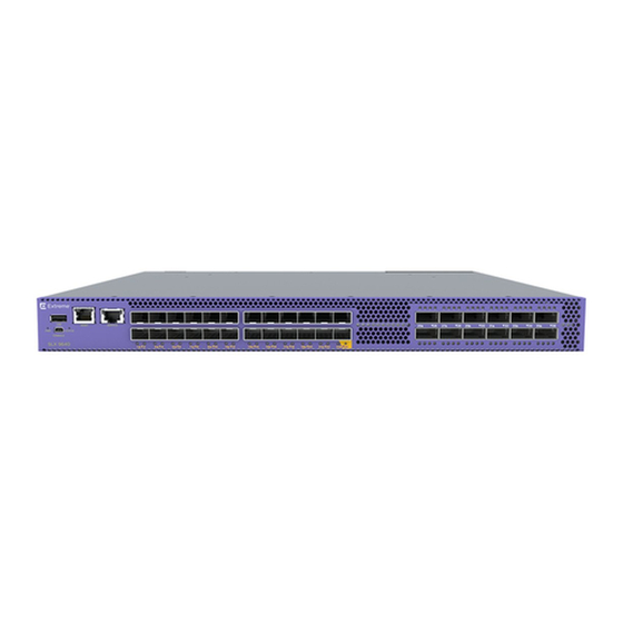
100 GbE QSFP-28, 40 GbE QSFP+, 10 GbE SFP+, 1 GbE SFP+ Packet buffers per switch 6 GB * Software upgrade licenses are available for the ExtremeRouting SLX 9640-24S for Ports on Demand (PoD) to enable 100 GbE/40 GbE ports. The following shows the front view of the SLX 9640 Router. -
Page 15: Nonport-Side View Of The Slx 9640 Switch Router
There are 12 QSFP28 ports numbered from P25 to P36. The port speeds for the QSFP28 ports are as follows: 1. 10Gb 2. 25Gb 3. 40Gb 4. 50Gb 5. 100Gb Nonport-side view of the SLX 9640 Switch Router The following illustration shows the rear-view or nonport-side of the SLX 9640 Switch Router. ExtremeRouting SLX 9640 Hardware Installation Guide... -
Page 16: Device Management Options
Ethernet or serial Extreme SLX-OS Management (CLI) connection Configuration Guide REST or NETCONF/YANG Ethernet connection Yes Extreme SLX-OS Management APIs. Configuration Guide Standard SNMP applications Ethernet or serial Extreme SLX-OS Management connection Configuration Guide ExtremeRouting SLX 9640 Hardware Installation Guide... -
Page 17: Preparing For The Installation
Caution Disassembling any part of the power supply and fan assembly voids the warranty and regulatory certifications. There are no user-serviceable parts inside the power supply and fan assembly. ExtremeRouting SLX 9640 Hardware Installation Guide... -
Page 18: Esd Precautions
Caution Before plugging a cable into any port, be sure to discharge the voltage stored on the cable by touching the electrical contacts to ground surface. ExtremeRouting SLX 9640 Hardware Installation Guide... -
Page 19: Power Precautions
Caution To prevent damage to the chassis and components, never attempt to lift the chassis using the fan or power supply handles. These handles were not designed to support the weight of the chassis. ExtremeRouting SLX 9640 Hardware Installation Guide... -
Page 20: Laser Precautions
Laser Radiation. Do Not View Directly with Optical Instruments. Class 1M Laser Products. Warning Use only optical transceivers that are qualified by Extreme Networks, Inc. and comply with the FDA Class 1 radiation performance requirements defined in 21 CFR Subchapter I, and with IEC 60825 and EN60825. -
Page 21: Shipping Carton Contents
◦ Two 6-ft. power cord ◦ Power cord retainer clip ◦ Rubber feet, required for setting up the device as a standalone unit China-RoHS Hazardous/Toxic Substance statement ◦ EULA/Read-Me document ◦ USB drive, 8G ExtremeRouting SLX 9640 Hardware Installation Guide... -
Page 22: Mounting The Device
17 before mounting the device. Note These rack mount kits are supported for this device at the date of this publication. For the latest support information, contact your Extreme Networks representative. Mounting precautions The following precautions specifically apply to mounting the device. -
Page 23: Standalone Installation
Installing the device in a rack Warning Make sure the rack housing the device is adequately secured to prevent it from becoming unstable or falling over. Note You need a #2 Phillips screwdriver for installation. ExtremeRouting SLX 9640 Hardware Installation Guide... -
Page 24: Four-Post Rack Mount Kit Installation (Xbr-R000297)
#2 Phillips torque screwdriver • 1/4-inch slotted-blade torque screwdriver Parts list The following parts are provided with the four-post flush-mount rack kit (XBR-R000297). Verify that the items below are included in the parts list. ExtremeRouting SLX 9640 Hardware Installation Guide... -
Page 25: Flush-Front Mounting
Complete the following tasks to install the device in a four-post rack. Attaching the front brackets on page 26. Installing the device in the rack on page 26. Attaching the rear brackets to the rack posts on page 27. ExtremeRouting SLX 9640 Hardware Installation Guide... - Page 26 Use the three holes in the bracket. 3. Attach the left front bracket to the left front rack post using three 10-32 x 5/8-in. panhead screws and three retainer nuts. Use the three holes in the bracket. ExtremeRouting SLX 9640 Hardware Installation Guide...
- Page 27 4. Attach the left rear bracket to the left rear rack post using three 10-32 x 5/8-in. panhead screws and three retainer nuts. Use the three holes in the bracket. 5. Tighten all the 10-32 x 5/8-in. screws to a torque of 25 in-lb (29 cm-kg). ExtremeRouting SLX 9640 Hardware Installation Guide...
-
Page 28: Installing The Universal Two-Post Rack Kit (Xen-R000294)
Figure 8: Attaching the rear brackets to the rack posts Installing the Universal Two-Post Rack Kit (XEN-R000294) Use the following instructions to install an Extreme Networks 1U or 2U device in a two-post telecommunications (Telco) rack using the Universal Two-Post Rack Kit (XEN-R000294). -
Page 29: Installation Requirements
The following parts are provided with the Universal Two-Post Rack Kit (XEN-R000294). Figure 9: XEN-R000294 Rack Parts list 1. Front brackets (2) 2. Rear brackets 5-6 inch post (2) 3. Rear brackets 3-5 inch post (2) ExtremeRouting SLX 9640 Hardware Installation Guide... -
Page 30: Flush-Front Mounting
Use the upper and lower screw holes, leaving the center holes empty. 3. Repeat step 1 and step 2 to attach the left front bracket to the left side of the device. ExtremeRouting SLX 9640 Hardware Installation Guide... - Page 31 Use the upper and lower holes in the bracket. 3. Attach the left front bracket to the left rack upright using two 10-32 x 5/8-in. panhead screws and two retainer nuts. Use the upper and lower holes in the bracket. ExtremeRouting SLX 9640 Hardware Installation Guide...
- Page 32 3. Attach the bracket to the right rack upright using two 10-32 x 5/8-in. panhead screws and two retainer nuts. Use the upper and lower holes in the bracket. 4. Repeat step 2 and step 3 to attach the left rear bracket to the left rack upright. ExtremeRouting SLX 9640 Hardware Installation Guide...
- Page 33 2. Align the left rear bracket to the left rear of the device and use four 8-32 x 5/16-in. panhead screws to attach the bracket to the device. Again, use the upper and lower slots in the bracket. ExtremeRouting SLX 9640 Hardware Installation Guide...
-
Page 34: Mid-Mounting
2. Insert four 8-32 x 5/16-in. flathead screws through the vertically aligned holes in the bracket and then into the holes on the side of the device. Use the upper and lower screw holes, leaving the center holes empty. ExtremeRouting SLX 9640 Hardware Installation Guide... - Page 35 Use the upper and lower holes in the bracket. 3. Attach the left front bracket to the left rack upright using two 10-32 x 5/8-in. screws and two retainer nuts. Use the upper and lower holes in the bracket. ExtremeRouting SLX 9640 Hardware Installation Guide...
- Page 36 3. Attach the brackets to the right rack upright using two 10-32 x 5/8-in. panhead screws and two retainer nuts. 4. Repeat step 2 and step 3 to attach the left rear bracket to the left rack upright. ExtremeRouting SLX 9640 Hardware Installation Guide...
- Page 37 2. Align the left rear bracket to the left rear of the device and use four 8-32 x 5/16-in. panhead screws to attach the bracket to the device. Again, use the upper and lower slots in the bracket. ExtremeRouting SLX 9640 Hardware Installation Guide...
-
Page 38: Installing The Universal Four-Post Rack Kit (Xen-R000296)
(L-5.0 to 32.0 in.), where L is the chassis depth, using the Universal Four-Post Rack Kit (XBR- R000296). There are two ways you can mount the device in a four-post rack: • With the port side flush with the front posts. ExtremeRouting SLX 9640 Hardware Installation Guide... - Page 39 Before mounting your device, review any specific installation and facility requirements in this Hardware Installation Guide. • Hardware devices illustrated in these procedures are only for reference and may not depict the device you are installing into the rack. ExtremeRouting SLX 9640 Hardware Installation Guide...
-
Page 40: Installation Requirements
The following items are required to install the device using the Universal Four-Post Rack Kit: • #2 Phillips torque screwdriver • 1/4-inch slotted-blade torque screwdriver Parts list The following parts are provided with the Universal Four-Post Rack Kit (XEN-R000296). ExtremeRouting SLX 9640 Hardware Installation Guide... - Page 41 6. Screw, 8-32 x 5/16-in., panhead Phillips (8) 7. Screw, 8-32 x 5/16-in., flathead Phillips (16) 8. Screw, 8-32 x 5/16-in., flathead Phillips (16) 9. Screw, 10-32 x 5/8-in., panhead Phillips (8) 10. Retainer nut, 10-32 (8) ExtremeRouting SLX 9640 Hardware Installation Guide...
-
Page 42: Flush-Front Mounting
Use the upper and lower screw holes, leaving the center holes empty. 3. Repeat step 1 and step 2 to attach the left front bracket to the left side of the device. ExtremeRouting SLX 9640 Hardware Installation Guide... - Page 43 Use the upper and lower screw holes, leaving the center holes empty. 4. Repeat step 2 and step 3 to attach the left bracket extension to the left side of the device. ExtremeRouting SLX 9640 Hardware Installation Guide...
- Page 44 Use the upper and lower holes in the bracket. 3. Attach the left front bracket to the left front rack post using two 10-32 x 5/8-in. panhead screws and two retainer nuts. Use the upper and lower holes in the bracket. ExtremeRouting SLX 9640 Hardware Installation Guide...
- Page 45 If possible, leave at least one empty vertical pair of holes between the screws for better support. 4. Repeat step 2 and 3 to attach the left rear bracket to the left bracket extension. ExtremeRouting SLX 9640 Hardware Installation Guide...
- Page 46 23. Use the upper and lower holes in the bracket. 2. Attach the left rear bracket to the left rear rack post using two 10-32 x 5/8-in. panhead screws and two retainer nuts. Use the upper and lower holes in the bracket. ExtremeRouting SLX 9640 Hardware Installation Guide...
-
Page 47: Flush-Rear (Recessed) Mounting
Attaching the extensions to the front of the device Installing the device in the rack Attaching the rear brackets to the extensions at the front of the device Attaching the rear brackets to the front rack posts ExtremeRouting SLX 9640 Hardware Installation Guide... - Page 48 1. Select the proper length extension bracket for your rack depth. 2. Position the right bracket extension along the side of the device as shown in Figure 25 on page 49. ExtremeRouting SLX 9640 Hardware Installation Guide...
- Page 49 Use the upper and lower holes in the bracket. 3. Attach the left front bracket to the left rear rack post using two 10-32 x 5/8-in. panhead screws and two retainer nuts. Use the upper and lower holes in the bracket. ExtremeRouting SLX 9640 Hardware Installation Guide...
- Page 50 52 for the positioning of the short or long brackets and screws. 3. Attach the brackets using four 6-32 x 1/4-in. panhead screws. 4. Repeat step 2 and step 3 to attach the left rear bracket to the left extension. ExtremeRouting SLX 9640 Hardware Installation Guide...
- Page 51 5. Adjust the brackets to the rack depth and tighten all the 6-32 x 1/4-in. screws to a torque of 9 in-lb (10 cm-kg). a. Rear brackets, short b. Screws, 6-32 x 1/4-in., panhead Phillips Figure 27: Attaching the rear brackets to the extensions at the front of the device ExtremeRouting SLX 9640 Hardware Installation Guide...
- Page 52 29. Use the upper and lower holes in the bracket. 2. Attach the left rear bracket to the left front rack post using two 10-32 x 5/8-in. screws and two retainer nuts. Use the upper and lower holes in the bracket. ExtremeRouting SLX 9640 Hardware Installation Guide...
- Page 53 3. Tighten all the 10-32 x 5/8-in. screws to a torque of 25 in-lb (29 cm-kg). a. Screws, 10-32 x 5/8-in., panhead Phillips b. Retainer nuts, 10-32 Figure 29: Attaching the rear brackets to the front rack posts ExtremeRouting SLX 9640 Hardware Installation Guide...
-
Page 54: Initial Setup And Verification
Customize the chassis and host Use the switch-attributes chassis-name and switch- names. attributes host-name commands to change the default host name. For more information, refer to Customizing the chassis and host names on page 60 . ExtremeRouting SLX 9640 Hardware Installation Guide... -
Page 55: Items Required
A workstation computer with an installed terminal emulator application, such as HyperTerminal for Windows. • An unused IP address with corresponding subnet mask and gateway address. • A serial cable (provided) with an RJ-45 connector. • Two Ethernet cables (one per management module). ExtremeRouting SLX 9640 Hardware Installation Guide... -
Page 56: Providing Power To The Device
2. Connect the RJ-45 serial cable provided with the device to the management Ethernet port of the device. Figure 30: Port-side view of the SLX 9640 Switch Router ExtremeRouting SLX 9640 Hardware Installation Guide... - Page 57 In a UNIX environment, enter the following string at the prompt: tip /dev/ttyb -9600 If ttyb is already in use, use ttya instead and enter the following string at the prompt: tip /dev/ttya -9600 ExtremeRouting SLX 9640 Hardware Installation Guide...
-
Page 58: Configuring A Static Ip Address
When you have assigned the IP address to management interface 1, you should also assign the IP address to management interface 2 if you have installed a second management module. device(config)# interface Management 1 device(config-Management-1)# no ip address dhcp device(config-Management-1)# ip address 10.24.85.81/20 ExtremeRouting SLX 9640 Hardware Installation Guide... -
Page 59: Establishing An Ethernet Connection
Perform the following steps to establish an Ethernet connection to the device. 1. Remove the shipping plug from the Ethernet port on the active management module. The active management module has the LED labeled ACTIVE on the front panel illuminated in blue. ExtremeRouting SLX 9640 Hardware Installation Guide... -
Page 60: Customizing The Chassis And Host Names
Enter configure terminal to enter global configuration mode. b. Enter switch-attributes chassis-name chassis-name, where chassis-name is the new chassis name. c. Enter exit to return to privileged EXEC mode. d. To verify the new chassis name, enter the show chassis command. ExtremeRouting SLX 9640 Hardware Installation Guide... -
Page 61: Configuring The Dns Service
• A Telnet session using the chassis management IP address. 3. Log in to the device using admin as your login name. If you have not changed the default password, use password for password. ExtremeRouting SLX 9640 Hardware Installation Guide... -
Page 62: Backing Up The Configuration
TFTP server address. • usb:// saves the running configuration to the USB drive attached to the device (for example, plugged into the USB port in the management module). ExtremeRouting SLX 9640 Hardware Installation Guide... -
Page 63: Installing Cable Management Kit
Initial Setup and Verification Installing cable management kit Installing cable management kit For more information about installing cable management, refer to managing cables section Managing cables on page 65. ExtremeRouting SLX 9640 Hardware Installation Guide... -
Page 64: Transceivers And Cables
Extreme Ethernet Optics Family Datasheet on https://cloud.kapostcontent.net/pub/a070d154- d6f1-400b-b2f0-3d039ae2f604/data-center-ethernet-optics-data-sheet and to the current SLX- OS18r.2.00 for ExtremeRouting SLX 9640 Release Notes . Time and items required The installation or replacement procedure for one transceiver takes less than 5 minutes. Ensure that the following items are available: •... -
Page 65: Precautions Specific To Transceivers And Cables
All fiber-optic interfaces use Class 1 lasers. Warning Use only optical transceivers that are qualified by Extreme Networks, Inc. and comply with the FDA Class 1 radiation performance requirements defined in 21 CFR Subchapter I, and with IEC 60825 and EN60825. Optical products that do not comply with these standards might emit light that is hazardous to the eyes. -
Page 66: Installing An Sfp+ Transceiver
1. Perform one of the following steps, depending on your transceiver type. • If the transceiver uses a pull tab, use the pull tab to help push the transceiver into the port until it is firmly seated and the latching mechanism clicks. ExtremeRouting SLX 9640 Hardware Installation Guide... - Page 67 Figure 34: Installing an SFP+ transceiver with bail latch into the interface module port Transceivers are keyed so that they can only be inserted with the correct orientation. If a transceiver does not slide in easily, ensure that it is correctly oriented. ExtremeRouting SLX 9640 Hardware Installation Guide...
-
Page 68: Replacing An Sfp+ Transceiver
If transceiver has a pull tab, grasp the pull tab and pull the transceiver straight out from the port. Note Grasp the pull tab near the body of the transceiver to reduce the chances of bending the pull tab. As the transceiver may be hot, avoid touching it. ExtremeRouting SLX 9640 Hardware Installation Guide... -
Page 69: Installing A Qsfp28 Transceiver
If using 40GbE-to-10GbE breakouts, each QSFP28 transceiver contains four individual 10 GbE ports. Be aware that any problems with one port could affect all four ports in the quad if the QSFP28 must be replaced. ExtremeRouting SLX 9640 Hardware Installation Guide... - Page 70 After insertion, the LEDs have the following status: • Off - no link • On - link, no traffic • Rapid flash - link with traffic • Slow flash (one second on, one second off) - beaconing feature ExtremeRouting SLX 9640 Hardware Installation Guide...
-
Page 71: Replacing A Qsfp28 Transceiver
Gently push the correctly oriented QSFP28 transceiver until the latching mechanism clicks. Note The following figure uses a generic interface module. Your interface module might look different. ExtremeRouting SLX 9640 Hardware Installation Guide... -
Page 72: Breakout Cables
For 4 x 10Gbe breakout: • 4 SFP+ 40GbE-to-10GbE copper breakout cables in 1m, 3m, or 5m or greater lengths. • 40G-QSFP-SR4-INT (with fiber breakout cables and additional 10GbE optics). ExtremeRouting SLX 9640 Hardware Installation Guide... -
Page 73: Verifying Transceiver Operation
When traffic is detected on the port, the light becomes blinking green. You can also enter the show interface status and show ip interface brief commands to verify proper transceiver operation. ExtremeRouting SLX 9640 Hardware Installation Guide... -
Page 74: Monitoring The Device
One status bicolor status LED (green and amber) • One fan bicolor status LED (green and amber) • One PSU bicolor status LED (green and amber) The figure below shows the LEDs on the SLX 9640 switch router front panel. ExtremeRouting SLX 9640 Hardware Installation Guide... -
Page 75: Led Indicators
Valid power. All monitored voltages are nominal Status (bicolor) Blinking Amber-Green Attention TBD by SW Amber Fault/ initial state This LED shall be lit during the reboot Green Board is operational 1G Ethernet Status ExtremeRouting SLX 9640 Hardware Installation Guide... - Page 76 Amber Steady Fan needs attention/ replacement 10G/100G Port LEDs (Green only) Solid Off No Link Solid ON Link, no traffic Mismatched airflow fan or fan runs below setting speed. Green Flicker Link, traffic Activities ExtremeRouting SLX 9640 Hardware Installation Guide...
- Page 77 One port LED on 2 sec, Off 2 sec Indicates a particular port fault. Home Run Port LEDs (Amber only. Note: This LED is shared with SFP Port 24 LED) Solid Off No Link Solid Amber ON Link, no traffic Amber Flicker Link, Activity ExtremeRouting SLX 9640 Hardware Installation Guide...
-
Page 78: Power Supplies
86 Power supply overview The ExtremeRouting SLX 9640 device supports alternating-current (AC) and direct-current (DC) power supplies. The SLX 9640 device is capable of running on one power supply and five fan assemblies. The second power supply and sixth fan assembly provide redundancy. - Page 79 • DC power supply with nonport-side air intake. This unit moves the air from the nonport-side to the port-side of the device. 1. Release lever 2. Power supply handle Figure 41: AC power supply ExtremeRouting SLX 9640 Hardware Installation Guide...
-
Page 80: Precautions Specific To Power Supplies
Caution Disassembling any part of the power supply and fan assembly voids the warranty and regulatory certifications. There are no user-serviceable parts inside the power supply and fan assembly. ExtremeRouting SLX 9640 Hardware Installation Guide... -
Page 81: Identifying The Airflow Direction
When installing or replacing a power supply unit, keep in mind the following: • Power supplies can be swapped in or out while the device is running. The remaining power supply provides enough power for the device. ExtremeRouting SLX 9640 Hardware Installation Guide... -
Page 82: Inserting A New Ac Power Supply
3. Before opening the package that contains the power supply, touch the bag to the switch casing to discharge any potential static electricity. Extreme recommends using an ESD wrist strap during installation. 4. Remove the power supply from the anti-static shielded bag. ExtremeRouting SLX 9640 Hardware Installation Guide... -
Page 83: Inserting A New Dc Power Supply
Note This equipment installation must meet NEC/CEC code requirements. Consult your local authorities for required regulations Use the following steps to install an DC power supply in the SLX 9640 device. ExtremeRouting SLX 9640 Hardware Installation Guide... - Page 84 5. Remove the DC power supply from the anti-static shielded bag. 6. Remove the DC terminals plastic cover. 7. Attach the safety grounding wire to the power supply using the safety ground screw. ExtremeRouting SLX 9640 Hardware Installation Guide...
- Page 85 2 - Safety ground screw Figure 45: DC power supply wiring terminals 9. Make sure the screws are tight with no wire touching the ground screw. Refer to the Figure below for an example of a suitable wiring. ExtremeRouting SLX 9640 Hardware Installation Guide...
-
Page 86: Grounding The Slx 9640 Device
Before connecting power to the device, the grounding terminal must be connected to ground to ensure proper operation and to meet electromagnetic interference (EMI) and safety requirements. ExtremeRouting SLX 9640 Hardware Installation Guide... - Page 87 5. Attach the grounding wire to a grounding point. Note The terminal for the connection of a grounding conductor is not to be used with an aluminum conductor. ExtremeRouting SLX 9640 Hardware Installation Guide...
-
Page 88: Fan Assemblies
91 Fan assemby overview The ExtremeRouting SLX 9640 device includes six redundant, hot-swappable fan units. However, the switch is capable of running on one power supply and five fans. The second power supply and sixth fan provide redundancy. -
Page 89: Precautions Specific To Fan Assemblies
Ensure that the airflow direction of the power supply unit matches that of the installed fan tray. The power supplies and fan trays are clearly labeled with either a green arrow with an "E", or an orange arrow with an "I." ExtremeRouting SLX 9640 Hardware Installation Guide... -
Page 90: Identifying The Airflow Direction
When installing or replacing a fan assembly unit, keep in mind the following: • Fan assemblies can be swapped in or out while the device is running. The remaining fan assemblies provide enough airflow for the device. ExtremeRouting SLX 9640 Hardware Installation Guide... -
Page 91: Inserting A New Fan Assembly
3. Before opening the package that contains the new fan assembly, touch the bag to the switch casing to discharge any potential static electricity. It is recommended that you wear an ESD wrist strap during installation. ExtremeRouting SLX 9640 Hardware Installation Guide... - Page 92 If you do not install a module or a power supply in a slot, you must keep the slot filler panel in place. If you run the chassis with an uncovered slot, the system will overheat. ExtremeRouting SLX 9640 Hardware Installation Guide...
-
Page 93: Extremerouting Slx 9640 Technical Specifications
100 GbE QSFP28 ports can support 40GE/4x10GE/ 100GE/4x25GE/2x50GE interfaces. SFP+ ports The SFP+ ports can support 10GbE/1GbE interfaces. There are 24 x SFP+ ports. Ethernet RJ-45 port with 10/100/1000 Mbps auto-negotiating management port capability ExtremeRouting SLX 9640 Hardware Installation Guide... -
Page 94: Leds
0°C to 40°C (32°F to 104°F) (F2B) -40°C to 70°C (-40°F to 158°F) temperature -5°C to 50°C (23°F to 122°F) (F2B) with 6 fan assemblies Relative humidity 5% to 95% at 50°C (122°F) 5% to 95% at 70°C (158°F) (non-condensing) ExtremeRouting SLX 9640 Hardware Installation Guide... -
Page 95: Power Supply Specifications (Per Psu)
566 BTU/hr 573 BTU/hr 1 x 650 W DC 178 W 176 W 179 W 1 x 650 W AC 2 power supplies 607 BTU/hr 601 BTU/hr 611 BTU/hr 1 x 650 W DC ExtremeRouting SLX 9640 Hardware Installation Guide... -
Page 96: Power Consumption (Maximum Configuration)
Logic ground Not supported Transmit data Not supported Not supported Serial port specifications (pinout - mini-USB) Signal Description Reserved Not used UART0_RX Debug port (data received by SLX) UART0_TX Console port (data transmitted by SLX) ExtremeRouting SLX 9640 Hardware Installation Guide... -
Page 97: Serial Port Specifications (Protocol)
EN 300 386 • CNS 13438 • KN 32 • KN 35 • TCVN 7189 • EN 61000-3-2 • EN 61000-3-3 • GB 9254 • CISPR 32 • 2014/30/EU • AS/NZS CISPR32 (Australia) (Class A) ExtremeRouting SLX 9640 Hardware Installation Guide... -
Page 98: Regulatory Compliance (Safety)
Conflict Minerals. • 30/2011/TT-BCT - Vietnam circular. • SJ/T 11363-2006 Requirements for Concentration Limits for Certain Hazardous Substances in EIPs (China). • SJ/T 11364-2006 Marking for the Control of Pollution Caused by EIPs (China). ExtremeRouting SLX 9640 Hardware Installation Guide... -
Page 99: Regulatory Statements
EN 55032/EN 55024 (European Immunity Requirements) ◦ EN61000-3-2/JEIDA (European and Japanese Harmonics Spec) ◦ EN61000-3-3 China ROHS Refer to the latest revision of the China ROHS document (P/N 53‐1000428‐xx) which ships with the product. ExtremeRouting SLX 9640 Hardware Installation Guide... -
Page 100: Bsmi Statement (Taiwan)
Canadian requirements This Class A digital apparatus meets all requirements of the Canadian Interference-Causing Equipment Regulations, ICES-003 Class A. Cet appareil numérique de la classe A est conforme à la norme NMB-003 du Canada. ExtremeRouting SLX 9640 Hardware Installation Guide... -
Page 101: China Ccc Statement
This equipment generates, uses, and can radiate radio frequency energy, and if not installed and used in accordance with the instruction manual, might cause harmful interference to radio communications. ExtremeRouting SLX 9640 Hardware Installation Guide... -
Page 102: Germany Statement
This is a Class A product based on the standard of the Voluntary Control Council for Interference by Information Technology Equipment (VCCI). If this equipment is used in a domestic environment, radio disturbance might arise. When such trouble occurs, the user might be required to take corrective actions. ExtremeRouting SLX 9640 Hardware Installation Guide... -
Page 103: Japan Power Cord
Regulatory Statements Japan power cord Japan power cord English translation of above statement ATTENTION: Never use the power cord packed with your equipment for other products. ExtremeRouting SLX 9640 Hardware Installation Guide... -
Page 104: Cautions And Danger Notices
Un mensaje de precaución le alerta de situaciones que pueden resultar peligrosas para usted o causar daños en el hardware, el firmware, el software o los datos. ExtremeRouting SLX 9640 Hardware Installation Guide... -
Page 105: General Cautions
Aucune pièce du bloc de l'alimentation ou du ventilateur ne peut être réparée par l'utilisateur. PRECAUCIÓN Si se desmonta cualquier pieza del módulo de fuente de alimentación y ventiladores, la garantía y las certificaciones normativas quedan anuladas. En el interior del ExtremeRouting SLX 9640 Hardware Installation Guide... - Page 106 PRECAUCIÓN Para evitar que se dañe el puerto serie, mantenga la cubierta colocada sobre el puerto cuando no lo utilice. Caution Never leave tools inside the chassis. Lassen Sie keine Werkzeuge im Chassis zurück. ExtremeRouting SLX 9640 Hardware Installation Guide...
- Page 107 Au cours de cette procédure, l'appareil doit être éteint et déconnecté du réseau. GARDE PRECAUCIÓN El dispositivo debe estar apagado y desconectado del fabric durante este procedimiento. ExtremeRouting SLX 9640 Hardware Installation Guide Caution All devices with DC power supplies are intended for installation in restricted access areas only.
- Page 108 überbelastet werden. Addieren Sie die Nennstromleistung (in Ampere) aller Geräte, die am selben Stromkreis wie das Gerät installiert sind. Somit können Sie feststellen, ob die Gefahr einer Überbelastung der Versorgungsstromkreise vorliegt. Vergleichen Sie diese Summe mit der Nennstromgrenze des Stromkreises. Die Höchstnennströme ExtremeRouting SLX 9640 Hardware Installation Guide...
- Page 109 Para prevenir daños al chasis y a los componentes, nunca intente levantar el chasis usando las asas de la fuente de alimentación o del ventilador. Tales asas no han sido diseñadas para soportar el peso del chasis. ExtremeRouting SLX 9640 Hardware Installation Guide...
-
Page 110: Danger Notices
Una advertencia de peligro indica condiciones o situaciones que pueden resultar potencialmente letales o extremadamente peligrosas. También habrá etiquetas de seguridad pegadas directamente sobre los productos para advertir de estas condiciones o situaciones. ExtremeRouting SLX 9640 Hardware Installation Guide... -
Page 111: General Dangers
Jetez/recyclez les batteries conformément aux normes locales. PELIGRO Las baterías usadas para respaldo de RTC/NVRAM no se encuentran en areas de acceso del operador. Existe riesgo de explosión si una batería es remplazada por un ExtremeRouting SLX 9640 Hardware Installation Guide... - Page 112 Antes de comenzar la instalación, consulte las precauciones en la sección “Power Precautions” (Precauciones sobre corriente). Warning ExtremeRouting SLX 9640 Hardware Installation Guide Be careful not to accidently insert your fingers into the fan tray while removing it from the chassis. The fan may still be spinning at a high speed.
- Page 113 警告 Warning Use only optical transceivers that are qualified by Extreme Networks, Inc. and comply with the FDA Class 1 radiation performance requirements defined in 21 CFR Subchapter I, and with IEC 60825 and EN60825. Optical products that do not comply with these standards might emit light that is hazardous to the eyes.
Need help?
Do you have a question about the ExtremeRouting SLX 9640 and is the answer not in the manual?
Questions and answers