
Related Manuals for Extreme Networks Extreme Wireless WSAP3825i


Summary of Contents for Extreme Networks Extreme Wireless WSAP3825i
-
Page 1: Installation Guide
™ ExtremeWireless AP3825i & WS-AP3825e Installation Guide 9034791-02 Published September 2016... - Page 2 Copyright © 2016 Extreme Networks, Inc. All rights reserved. Legal Notice Extreme Networks, Inc. reserves the right to make changes in specifications and other information contained in this document and its website without prior notice. The reader should in all cases consult representatives of Extreme Networks to determine whether any such changes have been made.
-
Page 3: Table Of Contents
Table of Contents Preface............................4 Text Conventions...................................4 Providing Feedback to Us..............................4 Getting Help.....................................5 Related Publications................................5 Chapter 1: About This Guide.....................6 Who Should Use This Guide............................6 How to Use This Guide............................... 6 Chapter 2: Introduction......................7 About the WS-AP3825i and WS-AP3825e......................7 WS-AP3825 Overview................................ -
Page 4: Preface
Preface Text Conventions The following tables list text conventions that are used throughout this guide. Table 1: Notice Icons Icon Notice Type Alerts you to... General Notice Helpful tips and notices for using the product. Note Important features or instructions. Caution Risk of personal injury, system damage, or loss of data. -
Page 5: Getting Help
Preface If you would like to provide feedback to the Extreme Networks Information Development team about this document, please contact us using our short online feedback form. You can also email us directly at internalinfodev@extremenetworks.com. Getting Help If you require assistance, contact Extreme Networks using one of the following methods: •... -
Page 6: Chapter 1: About This Guide
About This Guide Who Should Use This Guide How to Use This Guide The guide describes how to mount and connect cables to the ExtremeWireless ™ AP3825 access point. In addition, this guide provides information on the product certifications and national approvals for the WS-AP3825 access point. -
Page 7: Chapter 2: Introduction
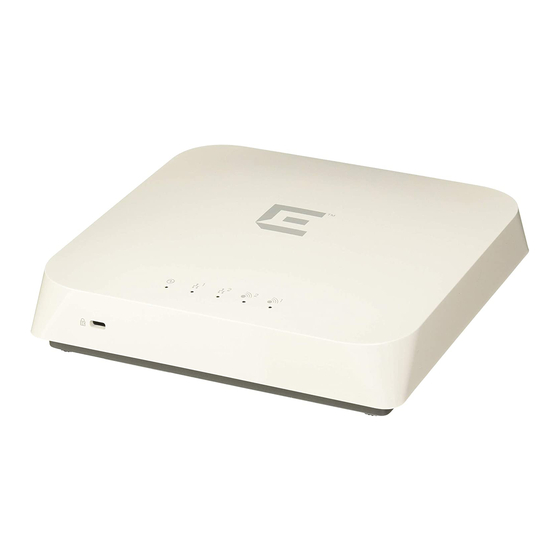
About the WS-AP3825i and WS-AP3825e The WS-AP3825i and WS-AP3825e access points are a cost-effective solution for extending your wireless LAN around indoor locations. They interoperate fully with the Extreme Networks wireless LAN, including support for Extreme Networks wireless VoWLAN, branch office mode, availability, and mobility features. - Page 8 10 shows the back view of the WS-AP3825e. The back panel is the same for both models, but there are no external antenna RSMA connectors on the WS-AP3825i. Figure 4 on page 11 illustrates the WS-AP3825 LEDs. Figure 1: Extreme Networks Wireless AP3825i Front View ExtremeWireless™ WS-AP3825i & WS-AP3825e Installation Guide for version .
- Page 9 External power supply port LEDs (See Figure 4 on page 11 for details) LAN port 1 (bottom) Slot for Kensington lock Figure 2: Extreme Networks Wireless AP3825e Front View (not used) Reset switch Console port LEDs (See Figure 4 on page 11 for details)
- Page 10 Introduction External power supply port (bottom) Slot for Kensington lock LAN port 1 RSMA External antenna connectors (6) LAN port 2 Figure 3: WS-AP3825 Back View RSMA antenna connectors (WS-AP3825e Mount Bracket only) Port Bay Mounting Slot WS-AP3825 LED Indicators Both models of the WS-AP3825 have four LED indicators, shown in Figure 4 below.
- Page 11 Introduction Figure 4: WS-AP3825 LEDs (Front, lower right) AP status Radio 2 status (2.4 GHz) LAN 1 (Ethernet 1) link state Radio 1 status (5 GHz) LAN 2 (Ethernet 2) link state Table 3: WS-AP3825 LED Indications Status Description 1 (AP status) On Green Indicates the WS-AP3825 is working normally.
-
Page 12: Architectural Features
Introduction Table 3: WS-AP3825 LED Indications (continued) Status Description 3 (Ethernet link state) LAN 2 On Green Indicates a valid 100Mbps Ethernet link. On Amber Indicates a valid 1Gbps Ethernet link. Indicates the link is down. 4 (Radio 2 status) On Green Indicates Radio 2 is enabled. - Page 13 Introduction Kensington Lock Slot There is a slot for a Kensington lock on the bottom side of the AP. See Kensington lock documentation for instructions on use of the lock. ExtremeWireless™ WS-AP3825i & WS-AP3825e Installation Guide for version .
-
Page 14: Chapter 3: Installation
Mounting brackets with screws Wall mounting screws and plastic anchors WS-AP3825 Quick Reference card 3 Perform a visual inspection of the AP for any signs of physical damage. Contact Extreme Networks if there are any signs of damage. Refer to Getting Help on page 5 for details. - Page 15 Installation Mounting the WS-AP3825 to a Drop Ceiling To mount the AP to a drop ceiling, use one of the mounting brackets provided with the AP. There are brackets for flat drop ceilings and protruded drop ceilings. • Flat Drop Ceiling Bracket Flat drop ceilings are those in which the ceiling tiles rest flat (or nearly so) on their supporting T-bar rails.
- Page 16 Installation Attach the T-bar rail mount bracket to the back of the AP by placing the bracket against the AP back, aligned as shown in Figure 5, with the bracket’s countersink screw holes matched up with the screw holes on the AP. Screw the provided screws into the mounting bracket and AP as shown in Figure Figure 5: Attaching a Mount Bracket to the AP back 2 Remove the ceiling panels around the drop ceiling T-bar rails where you intend to mount the AP.
- Page 17 Installation 3 Hold the AP with the bracket against the flat side of the T-bar rail and (nearly) parallel to it. The clamping tabs fit over the rail easily if you slide one bracket tab over the lip of the rail, at a very slight angle to the rail, and then press the AP up against the rail (so that the opposite clamping tab clears the rail) and twist it so that the opposite clamping tab slides over the opposite rail lip as shown in Figure...
- Page 18 Installation 4 When the bracket is aligned with the rail again, both clamping tabs are positioned on the T-bar rail lips. Figure 7 shows a mounting bracket, with an AP attached, firmly mounted on a drop-ceiling T- bar rail. Tap the AP to verify it is stable and won't fall off. Figure 7: AP and Mounting Bracket Seated on T-bar Rail 5 Make a hole through the ceiling panel closest to the connector bay on the AP.
- Page 19 Installation 2 Drill two holes in the wall to match the center of the two keyhole slots in the back of the AP. The location of the holes is depicted in Figure 8 (measurements are in millimeters). For a tight fit, the holes should be slightly smaller than the diameter of the provided plastic anchors.
- Page 20 Installation 4 Place the back of the AP against the wall with the protruding mounting screw heads fitting through the keyhole slots on the back of the AP, and slide the AP down until the AP rests on the mounting screw heads.
- Page 21 Installation Figure 10: Mounting Bracket: WS-MBI-DCU01 To install the mounting bracket: ExtremeWireless™ WS-AP3825i & WS-AP3825e Installation Guide for version .
- Page 22 Installation Attach the WS-MBI-DCU01 to the AP using the screws provided. If needed, pull the handle and slide the top piece to access the additional screw holes that are underneath the handle. The four screw holes are indicated by the green arrows in the following figure: Figure 11: Sliding Handle and Screw Holes...
- Page 23 Installation WS-MBI-WALL-01 Mounting Bracket on Junction/Gang Box The WS-MBI-WALL-01 can be mounted on a junction/gang box, wall, or a solid ceiling. When mounting on a solid ceiling, it is required that you use a Kensington lock or an equivalent lock. Figure 12: WS-MBI-WALL-01 Bracket To mount the WS-MBI-WALL-01 bracket on a junction or gang box: Put the center of the bracket as close as possible to the center of the box.
- Page 24 Installation WS-MBI-WALL-01 Mounting Bracket on Wall or Solid Ceiling The WS-MBI-WALL-01 can be mounted on a junction/gang box, wall, or a solid ceiling. When mounting on a solid ceiling, it is required that you use a Kensington lock or an equivalent lock. To mount the WS-MBI-WALL-01 bracket on a wall or solid ceiling: Figure 13: Beveled Holes for Wall or Solid Ceiling Mounting (WS-MBI-WALL-01) 2 Mark the centers of the four beveled hole locations.
-
Page 25: Configuring Ap Channel Settings
Installation The WS-AP3825 has both a LAN and a Console port. Refer to Figure 1-1 on page 1-2 for the location of these ports. During administration and maintenance through the LAN or Console, the AP must have a power connection through either an Ethernet PoE cable or a DC power supply. Power Connections The AP can be powered in one of the following ways: •... - Page 26 Installation Configuring Radio RF Port The professional installer configures Radio RF ports where antenna ports will be connected. Note All professional antenna model names are prefixed with PRO. To configure Radio RF Ports through the ExtremeWireless Assistant: Log into the Wireless Assistant. 2 From the top menu, click AP.
- Page 27 Installation 4 Click Professional Install. The Professional Install Dialog displays. 5 Modify the Radio Antenna Type as follows: • If attaching triple port antennas, all three RF port should be configured with the same antenna type. • If attaching dual port antennas, two of the radio RF ports should be configured with the same antenna type and the third (non-active port) should be configured to None.
- Page 28 Installation 3 Configure the desired Radio Mode, and Channel Width. 4 From the Request a New Channel drop-down menu, select a channel according to the site channel plan. 5 Request the AP to auto select the channel from the channel list set in the Channel Plan setting. 6 Repeat the process for Radio 2.
- Page 29 Installation Configuring Radio Transmit (Tx) Power Based on the configured mode, channel, channel plan, and channel width for the specific antenna, the professional installer must enter the corresponding Transmit Power (Tx Power) for the desired Radio using the ExtremeWireless Assistant. Log into the Wireless Assistant.
-
Page 30: Appendix A: Specifications
Specifications External Power Supplies Internal Antenna Access Points External Antennas This appendix lists the specifications for the WS-AP3825i and WS-AP3825e access points and an external 12V DC power supply. Table 5: Specifications for the WS-AP3825i and WS-AP3825e Item Specification Enclosure material Metal base, plastic housing Power source 802.3af compliant PoE PD,... -
Page 31: Internal Antenna Access Points
Item Specification Output current (max) Output power (max) Table 7 lists recommended power supplies for the WS-AP3825, by country: Table 7: Recommended DC Power Supplies for WS-AP3825 Country Extreme Networks Part Number Australia WS-PS3X12-AU Brazil WS-PS3X12-BR China WS-PS3X12-CN WS-PS3X12-EU WS-PS3X12-UK... - Page 32 Specifications Figure 14: Horizontal Radiation Pattern 2.4 GHz ExtremeWireless™ WS-AP3825i & WS-AP3825e Installation Guide for version .
- Page 33 Specifications Figure 15: Vertical XZ Radiation Pattern 2.4 GHz ExtremeWireless™ WS-AP3825i & WS-AP3825e Installation Guide for version .
- Page 34 Specifications Figure 16: Vertical YZ Radiation Pattern 2.4 GHz ExtremeWireless™ WS-AP3825i & WS-AP3825e Installation Guide for version .
- Page 35 Specifications Figure 17: Horizontal Radiation Pattern 5 GHz ExtremeWireless™ WS-AP3825i & WS-AP3825e Installation Guide for version .
- Page 36 Specifications Figure 18: Vertical XZ Radiation Pattern 5 GHz ExtremeWireless™ WS-AP3825i & WS-AP3825e Installation Guide for version .
-
Page 37: External Antennas
Specifications Figure 19: Vertical YZ Radiation Pattern 5 GHz External Antennas Table 9 lists the certified external antennas for WS-AP3825e. For more detailed specifications and radiation pattern diagrams, see the ExtremeWireless External Antenna Site Preparation and Installation Guide. Table 9: Certified External Antennas for WS-AP3825e Model Application Description... - Page 38 Specifications Table 9: Certified External Antennas for WS-AP3825e (continued) Model Application Description Gain (dBi) Frequency (GHz) Connector Type WS-AI-DX10055 Indoor MIMO; Sector, 10 dBi 2.4 – 2.5, RSMA Dualband 6 dBi 5.1 – 5.9 WS-AI-DX07025 Indoor MIMO; Sector; 6.5 dBi 2.4 –...
-
Page 39: Appendix B: Regulatory Information
Warning Changes or modifications made to the ExtremeWireless AP3825 which are not expressly approved by Extreme Networks could void the user's authority to operate the equipment. Only authorized Extreme Networks service personnel are permitted to service the system. Procedures that should be performed only by Extreme Networks personnel are clearly identified in this guide. - Page 40 This Part 15 radio device operates on a non-interference basis with other devices operating at the same frequency when using the antennas provided or other Extreme Networks-certified antennas. Any changes or modifications to the product not expressly approved by Extreme Networks could void the user's authority to operate this device.
- Page 41 Regulatory Information The radiated output power of the ExtremeWireless AP3825 is below the FCC radio frequency exposure limits as specified in “Guidelines for Human Exposure to Radio Frequency Electromagnetic Fields” (OET Bulletin 65, Supplement C). This equipment should be installed and operated with a minimum distance of 20 cm between the radiator and your body or other colocated operating antennas.
-
Page 42: European Community
Regulatory Information 5470-5850 MHz et que ces radars pourraient causer du brouillage et/ou des dommages aux dispositifs LAN-EL. • Pour le produit disponible sur le marché canadien, seuls les canaux 1 à 11 peuvent être utilisés. Il est impossible de sélectionner d’autres canaux dans la bande de 2.4 GHz. •... - Page 43 The ExtremeWireless AP3825 is intended for indoor use and must be installed in a proper indoor location. Contact local Authority for procedure to follow and regulatory information. For more details on legal combinations of frequencies, power levels and antennas, contact Extreme Networks. Declaration of Conformity with R&TTE Directive of the European Union 1999/5/EC The following symbol indicates compliance with the Essential Requirements of the R&TTE Directive of...
- Page 44 ΤΙΣ ΟΥΣΙΩΔΕΙΣ ΑΠΑΙΤΗΣΕΙΣ ΚΑΙ ΤΙΣ ΛΟΙΠΕΣ ΣΧΕΤΙΚΕΣ ΔΙΑΤΑΞΕΙΣ ΤΗΣ ΟΔΗΓΙΑΣ 1999/5/ΕΚ. Icelandic Extreme Networks lysir her med yfir að thessi bunadur, Radio LAN device, uppfyllir allar grunnkrofur, sem gerdar eru i R&TTE tilskipun ESB nr 1999/5/EC. Con la presente Extreme Networks dichiara che questo Italian Radio LAN device è...
- Page 45 Regulatory Information European Conformance Standards This equipment meets the following conformance standards: Safety • 2006/95/EC Low Voltage Directive (LVD) • IEC/EN 60950-1 + National Deviations EMC (Emissions / Immunity) • 2004/108/EC EMC Directive • EN 55011/CISPR 11, Class B, Group 1 ISM •...
- Page 46 Regulatory Information Caution Please follow the instructions in this user guide to configure the ExtremeWireless AP3825. • Each Wireless AP is configured with a default group of settings. There is the ability to change these settings. The user or installer is responsible to ensure that each ExtremeWireless AP3825 is configured properly.
-
Page 47: Certifications Of Other Countries
Regulatory Information Table 10: European Spectrum Usage Rules (continued) Country 5.15-5.25 (GHz) 5.25-5.35 (GHz) 5.47-5.725 (GHz) 2.4-2.4835 (GHz) Channels: Channels: Channels: Channels: 1 to 13 36,40,44,48 52,56,60,64 100,104,108,112,116, (Except Where 132,136,140 Noted) Hungary Indoor only Indoor only Indoor or outdoor Indoor or outdoor Iceland Indoor only... - Page 48 Regulatory Information • AS/NZS 3548 (Emissions via EU standards – ACMA) • AS/NZS 4288 (Radio via EU standards) • EN 300 328 (2.4 GHz) • EN 301 893 (5 GHz) • EN 301 489-1 & -17 (RLAN) • IEEE 802.11a (5 GHz) •...
Need help?
Do you have a question about the Extreme Wireless WSAP3825i and is the answer not in the manual?
Questions and answers