Table of Contents
Advertisement
Quick Links
One Technology Way • P.O. Box 9106 • Norwood, MA 02062-9106, U.S.A. • Tel: 781.329.4700 • Fax: 781.461.3113 • www.analog.com
Evaluating the
ADP5360
FEATURES
VBUS input voltage: 4.0 V to 6.5 V
Fully featured evaluation board for the
Evaluation software and installation CD included
Simple device measurements and demonstrable with
A voltage power supply
A battery or battery simulator
A voltage meter
Load resistors or an electrical load
EQUIPMENT NEEDED
USB to I
2
C dongle
USB-SDP-CABLEZ
evaluation kit and must be ordered separately)
Li-ion battery or battery simulator
PC running Windows® 10 operating system
DOCUMENTS NEEDED
ADP5360 data sheet
SOFTWARE NEEDED
ADP5360 GUI Tool Software
PLEASE SEE THE LAST PAGE FOR AN IMPORTANT
WARNING AND LEGAL TERMS AND CONDITIONS.
Advanced Battery Management PMIC with Ultralow I
and Buck Boost
ADP5360
(not included in the
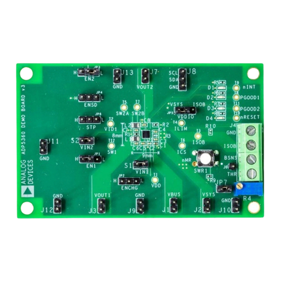
EVALUATION BOARD PHOTOGRAPH
Figure 1.
Rev. 0 | Page 1 of 18
ADP5360CB-EVALZ
GENERAL DESCRIPTION
This user guide describes the hardware and software used in the
ADP5360CB-EVALZ evaluation board and includes detailed
schematics and printed circuit board (PCB) layouts.
The
ADP5360
includes a high performance linear regulator for
single Li-ion/Li-ion battery charging, ultralow quiescent current
fuel gauge and battery protection circuit, an ultralow quiescent
buck and a buck boost switching regulator, and a supervisory
circuit.
The ADP5360CB-EVALZ evaluation board supports an
external USB dongle connection and the graphic user interface
(GUI) software allows the user to evaluate the comprehensive
functionalities provided by the I
The
ADP5360
operates over the −40°C to +85°C junction
temperature range and is available in a 32-ball, 2.56 mm ×
2.56 mm WLCSP.
More information on the
ADP5360
data sheet, available from www.analog.com, which must be
consulted in conjunction with this evaluation board user guide.
User Guide
UG-1571
Buck
Q
2
C interface.
is provided in the
ADP5360
Advertisement
Table of Contents

Subscribe to Our Youtube Channel
Related Manuals for Analog Devices ADP5360


Summary of Contents for Analog Devices ADP5360
-
Page 1: Features
ADP5360 SOFTWARE NEEDED data sheet, available from www.analog.com, which must be ADP5360 GUI Tool Software consulted in conjunction with this evaluation board user guide. EVALUATION BOARD PHOTOGRAPH Figure 1. PLEASE SEE THE LAST PAGE FOR AN IMPORTANT Rev. -
Page 2: Table Of Contents
Installing LabVIEW ..............3 Battery Protection Function Evaluation ........13 Installing the ADP5360 GUI Software ........3 Buck Regulator Evaluation ............13 Installing the SDP Drivers ............4 Buck Boost Regulator Evaluation ..........14 ... -
Page 3: Installing The Software
ADP5360CB-EVALZ User Guide UG-1571 INSTALLING THE SOFTWARE ADP5360 GUI Tool Software evaluates all functions and Click the Next button to install the software to the default features of the program registers. destination folder or click the Browse… button to choose a different file (see Figure 3). -
Page 4: Installing The Sdp Drivers
INSTALLING THE DRIVERS After clicking the Install button, the next window, shown To install the Analog Devices, Inc., system demonstration in Figure 8, appears. Click the Finish button to complete the platform (SDP) drivers, complete the following steps: driver installation. - Page 5 ADP5360CB-EVALZ User Guide UG-1571 To verify that the USB driver is installed properly, click the When the USB dongle is connected to a PC port that is different Start menu. Select Control Panel > System and open the from the one used to install the driver, the PC device driver may Device Manager window shown in Figure 9 to check if require the user to install the driver again for that specific port.
-
Page 6: Using The Adp5360 Gui Software
10°C and 45°C. If the ISOB and GND (see Figure 17). THR resistance does correspond with the battery Click Start > All Programs > ADP5360 GUI 1v0 > temperature, the THR Status, located in the ADP5360 GUI. -
Page 7: Battery Fuel Gauge Settings
The Battery SoC %, Battery Voltage (V), and BAT_SOCACM % values are read in the tab in Figure 11. tion data, then click the Program SoC Curve button to write all data to the ADP5360. The GUI then updates the Battery SoC Figure 11. ADP5360 GUI Software, Fuel Gauge Control Tab Rev. -
Page 8: Buck And Buck Boost Settings
Power Good Setting and Indicate box. the Supervisory Setting section located on the bottom left of the GUI (see Figure 12). Figure 12. ADP5360 GUI Software, Buck & BCKBST Control Tab Rev. 0 | Page 8 of 18... -
Page 9: Direct Register Write And Read
Some registers, such as Register 0x00 and Register 0x01, are read only registers and cannot be overwritten. Figure 13. ADP5360 GUI Software, Register R&W Tab Figure 14. ADP5360 GUI Software, Fuel Gauge Data Log Tab... -
Page 10: Gui Troubleshooting
(see Figure 16), this may mean the I C bus is not shown in Figure 15 appears. This issue may be because the detecting the ADP5360. Check that the cable is securely USB-SDP-CABLEZ is not connected to the computer. -
Page 11: Using The Evaluation Board
ADP5360CB-EVALZ evaluation board. Set the dc power supply to 5 V and connect the power Set the ENSD jumper high to enable ADP5360 shutdown mode. supply to the on-board VBUS and GND to a dc power After a Li-ion battery or battery simulator is connected to the supply. -
Page 12: Evaluation Board Measurements
Input Current Limit Parameter Control box (see Figure 10). The default value The input current-limit function of the ADP5360 can be is 4.16 V. The device is operating in constant voltage mode evaluated in fast CC charging mode. An additional system load upon power-up. -
Page 13: Battery Protection Function Evaluation
ADP5360CB-EVALZ User Guide UG-1571 BATTERY PROTECTION FUNCTION EVALUATION To enable the overdischarge current protection, set the VSYS load current (see Figure 17) at the system output to the default All battery protection voltage and current threshold settings, OC_DISCH, battery OC threshold value (see Figure 18). Next, hysteresis setting, and deglitch time is set up in the Battery check that the battery ISOB node is isolated from the VSYS Protection Setting section, under the Charge Control tab,... -
Page 14: Buck Boost Regulator Evaluation
BUCK BOOST REGULATOR EVALUATION RESET WD button, located above the WD_TIME box, to Set the EN_BUCKBST bit (see Figure 22) high to enable the toggle the ADP5360 watchdog. buck boost regulator. The default buck boost regulator output voltage is 5 V. -
Page 15: Evaluation Board Schematics And Artwork
ADP5360CB-EVALZ User Guide UG-1571 EVALUATION BOARD SCHEMATICS AND ARTWORK Figure 24. Evaluation Board Schematic of the ADP5360CB-EVALZ Evaluation Board Rev. 0 | Page 15 of 18... - Page 16 UG-1571 ADP5360CB-EVALZ User Guide Figure 25. Top Layer, Recommended Layout for the ADP5360CB-EVALZ Evaluation Board Figure 26. Second Layer, Recommended Layout for the ADP5360CB-EVALZ Evaluation Board Figure 27. Third Layer, Recommended Layout for the ADP5360CB-EVALZ Evaluation Board Rev. 0 | Page 16 of 18...
- Page 17 ADP5360CB-EVALZ User Guide UG-1571 Figure 28. Bottom Layer, Recommended Layout for the ADP5360CB-EVALZ Evaluation Board Rev. 0 | Page 17 of 18...
-
Page 18: Ordering Information
By using the evaluation board discussed herein (together with any tools, components documentation or support materials, the “Evaluation Board”), you are agreeing to be bound by the terms and conditions set forth below (“Agreement”) unless you have purchased the Evaluation Board, in which case the Analog Devices Standard Terms and Conditions of Sale shall govern. Do not use the Evaluation Board until you have read and agreed to the Agreement.
Need help?
Do you have a question about the ADP5360 and is the answer not in the manual?
Questions and answers