Table of Contents
Advertisement
Quick Links
One Technology Way • P.O. Box 9106 • Norwood, MA 02062-9106, U.S.A. • Tel: 781.329.4700 • Fax: 781.461.3113 • www.analog.com
FEATURES
Flexible inertial sensor evaluation platform
Single main board operates with interchangeable satellite
boards
Separates DUT from controller for accurate environmental
testing
500 Hz data rate SPI interface
Continuous stream to file data recording
Standard USB cable for power and communications
PC-based graphical user interface (GUI)
Fast, easy installation
GENERAL DESCRIPTION
The ADXRS800 inertial sensor evaluation system is an easy-to-
use evaluation tool targeting bench or desktop characterization
of Analog Devices, Inc., inertial sensor products. The system
consists of the inertial sensor evaluation board (ISEB), or main
board, and a satellite board for any Analog Devices inertial sensor
product. The ISEB connects directly to a PC via a USB cable,
with the USB connection providing both power and commun-
ications to the board. The ISEB is connected to the satellite
board through a ribbon cable. This cable allows the satellite to
be easily manipulated for testing or separately placed into an
environmental chamber for temperature or humidity testing.
Separating the boards mitigates corruption of data due to the
temperature and humidity effects of other components.
The ISEB is a universal main board and is intended to be used
with various satellites of Analog Devices inertial sensors, including
analog and digital accelerometers and gyroscopes. The different
products are evaluated by means of separate GUIs that are
customized for performance and characterization measurements
relevant to the inertial sensor being evaluated.
The EVAL-ADXRS800Z-M system contains the ISEB and the
EVAL-ADXRS800Z-S satellite. Also included is a USB A to
Mini-B cable to connect the ISEB to a PC and an 18 inch, 20-pin
PLEASE SEE THE LAST PAGE FOR AN IMPORTANT
WARNING AND LEGAL TERMS AND CONDITIONS.
Arrow.com.
Downloaded from
ADXRS800 Sensor Evaluation System
Rev. 0 | Page 1 of 16
Evaluation Board User Guide
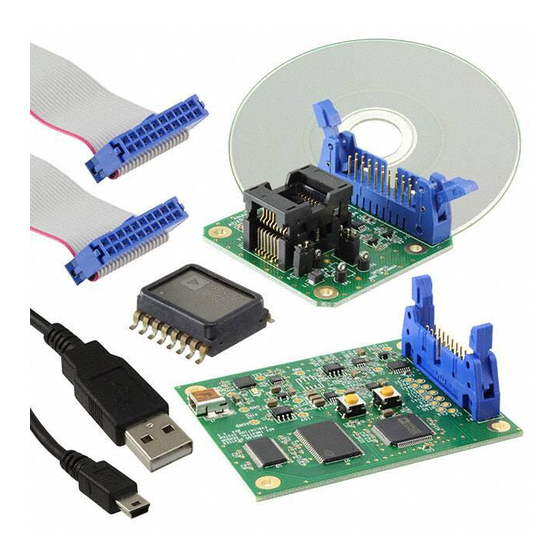
Figure 1. Inertial Sensor Evaluation System
ribbon cable to connect the ISEB to the satellite. A CD is
included with the necessary drivers and installers to use the
system and to quickly begin evaluating the ADXRS800.
INSTALLATION PROCEDURE
The following steps must be completed, in the order listed, to
successfully set up and run the ADXRS800 evaluation system:
1.
Download all CD-ROM files to the PC hard drive.
2.
Install the USB drivers for the inertial sensor evaluation
system (ISEB).
3.
Connect the ISEB hardware to the PC.
4.
Install the latest firmware revision into the ISEB hardware
(included on the CD-ROM).
5.
Install the ADXRS800 evaluation system GUI.
6.
Configure the ISEB hardware.
7.
Launch the ADXRS800 evaluation system GUI and test
devices.
This guide is designed to provide all the detail necessary to
install and operate the ADXRS800 evaluation system.
UG-154
Advertisement
Table of Contents

Related Manuals for Analog Devices ADXRS800


Summary of Contents for Analog Devices ADXRS800
-
Page 1: Features
(ISEB), or main INSTALLATION PROCEDURE board, and a satellite board for any Analog Devices inertial sensor The following steps must be completed, in the order listed, to product. The ISEB connects directly to a PC via a USB cable,... -
Page 2: Table Of Contents
UG-154 Evaluation Board User Guide TABLE OF CONTENTS Features ....................1 Getting Started ................8 General Description ................. 1 View and Record Data Panel ............9 Installation Procedure ..............1 Temperature Test Panel ............. 10 ... -
Page 3: Inertial Sensor Evaluation System Setup
Before proceeding with the installation routine, it is important process. to first download all files included on the ADXRS800 install- The ISEB should be detected automatically in the Device ation CD-ROM to a local folder on the host PC. Browse to a... -
Page 4: Installing The Latest Iseb Firmware
ISEB microcontroller. In addition, as new firmware is made available, it can be downloaded from the Analog Devices website (www.analog.com). To flash the ISEB microcontroller, follow these steps: Ensure that the ISEB is connected to and detected by the PC. - Page 5 If the firmware on the CD is used to flash the ISEB, the evaluation GUI on the corresponding CD is sufficient. If the firmware used is obtained from the Analog Devices website (www.analog.com), the most recent version of the evaluation GUI, which is also located on the website, should be used.
- Page 6 UG-154 Evaluation Board User Guide Figure 13. Start Installation (Listing Varies Based on PC Requirements) Figure 11. ADXRS800 Evaluation Software Installation Welcome From this point, complete the following steps to install the evaluation software: Select the destination directory. The installer autopopulates...
-
Page 7: Hardware Configuration
To configure the hardware, follow these steps: inserting it backward and causing damage to the system. If the hardware is not already connected, plug the USB A to Connect the ADXRS800 satellite to the opposite end of the Mini-B cable into the PC. ribbon cable. -
Page 8: Inertial Sensor Evaluation System Graphical User Interface
When the software GUI is closed, reset the ISEB evaluation & LTP) submenu to determine which COM port is assigned to the Analog Devices inertial sensor evaluation system. Select this board by pressing the reset button (SW2). COM port from the drop-down menu, and click Confirm Restart the software GUI. -
Page 9: View And Record Data Panel
This includes the fault register, sequence bits, status bits, and sensor module bits. This beneath the graph, contains the following three options: information is described in detail in the ADXRS800 data sheet. • Do Nothing (the default option) This information is also recorded alongside the plotted signals •... -
Page 10: Temperature Test Panel
Note that any offset correction made to the rate. The panel is specifically designed for temperature testing, ADXRS800 is stored in the device EEPROM indefinitely or with the on-board temperature sensor output plotted alongside until overwritten with a subsequent correction value. Any null the device rateout, filtered self-test, and quadrature. -
Page 11: Noise And Root Allan Variance Panel
RAV plot. variance can be approximately described as the variation of Determining the rms noise of the ADXRS800 can be done on successive long-term averages of the null output of the this same panel. The evaluation GUI calculates the rms noise by ADXRS800. -
Page 12: Turn-On Bias Stability Panel
UG-154 Evaluation Board User Guide TURN-ON BIAS STABILITY PANEL Figure 21. Turn-On Bias Stability Panel Another key performance characteristic of gyroscopes is their a file name for the data upon completion of the specified number turn-on to turn-on bias stability, which determines the range of of turn-on cycles or upon clicking the Stop Data Record button. -
Page 13: Turn-On Bias Settling Panel
The recommended the satellite board. turn-on time for the ADXRS800 is 100 ms (typical), and it is Additionally, if the device is rotated at a constant rate while not recommended that your applications try to obtain accurate power is applied, the Turn-on Bias Settling panel (see Figure 22) rate data from the device within this period. -
Page 14: Sensitivity Check Panel
UG-154 Evaluation Board User Guide SENSITIVITY CHECK PANEL Figure 23. Sensitivity Check Panel The last panel (see Figure 23) provides a method for checking After the null calibration is performed, slowly rotate the satellite board through 180° (90° can also be used). Because the approximate sensitivity of a given device. -
Page 15: Alternate External High Voltage Supply
To ensure that between 0.1 mA and See the ADXRS800 data sheet for a full description of the boost 1 mA of current is sourced, a 12 kΩ resistor can be chosen. This converter operation. -
Page 16: Header Pinout
By using the evaluation board discussed herein (together with any tools, components documentation or support materials, the “Evaluation Board”), you are agreeing to be bound by the terms and conditions set forth below (“Agreement”) unless you have purchased the Evaluation Board, in which case the Analog Devices Standard Terms and Conditions of Sale shall govern. Do not use the Evaluation Board until you have read and agreed to the Agreement.
Need help?
Do you have a question about the ADXRS800 and is the answer not in the manual?
Questions and answers