Sign In
Upload
Manuals
Brands
Festo Manuals
Touch terminals
VTSA-F-CB
Festo VTSA-F-CB Valve Terminal Manuals
Manuals and User Guides for Festo VTSA-F-CB Valve Terminal. We have
3
Festo VTSA-F-CB Valve Terminal manuals available for free PDF download: Manual, Instructions, Assembly, Installation
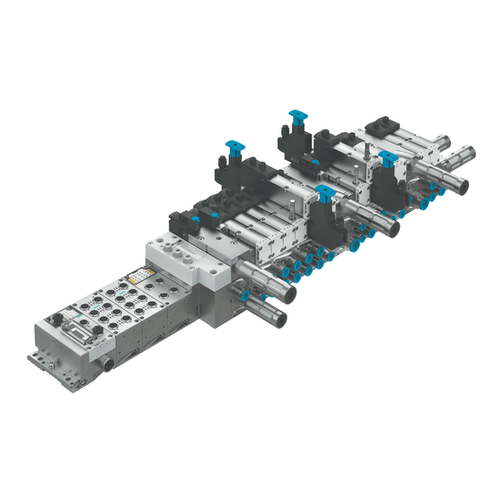
Festo VTSA-F-CB Manual (116 pages)
Valve terminal
Brand:
Festo
| Category:
Touch terminals
| Size: 14 MB
Table of Contents
Table of Contents
3
1 About this Document
7
Applicable Documents
7
Product Labelling
7
Specified Standards
8
2 Safety
9
General Safety Instructions
9
Intended Use
9
Foreseeable Misuse
9
Requirements for Product Use
9
Training of Qualified Personnel
9
Range of Application and Certifications
10
3 Further Information
10
4 Service
10
5 Product Overview
10
Function
10
Functions Pneumatics
10
Pressure Supply to the Valve Terminal
10
Pilot Air Supply
10
Pilot Exhaust Air
11
Creation of Pressure Zones
11
Vertical Stacking
14
Electrical Functions
14
Formation of Voltage Zones
14
Configuration
21
Pneumatic Components
21
Valves
22
Manifold Sub-Bases
25
Supply Plates
26
Right End Plates
27
Soft Start Valves with Pressure Monitoring
28
Pilot Air Valves with Pressure Sensing
31
Pressure Regulator Plates
33
Vertical Supply Plates
37
Throttle Plate
38
Vertical Pressure Shut-Off Plates
39
Vacuum Generator (Optional)
40
Separating Seals for Pressure Zone Formation
41
Electrical Components
43
Pneumatic Interface
43
Display Elements of the Pneumatic Components
46
Display Elements of the Electrical Components
47
Control Elements of the Pneumatic Components
48
Manual Override (MO)
48
Connecting Elements of the Pneumatic Components
50
Connection Elements of the Electrical Components
51
Labelling Elements
51
Operating Modes
52
Vacuum or Low-Pressure Operation
52
Reverse Operation
52
Address Assignment
53
Address Assignment of the Working Valves
53
Address Assignment of the Special Valves
54
Address Assignment of the Vacuum Generator
54
6 Transport and Storage
54
7 Mounting
55
Mounting Types
55
Mounting the Labelling Elements
55
Mounting/Dismounting the Identification Holder
55
8 Installation
56
Installation Pneumatics
56
Compressed Air Preparation
56
Operation with Unlubricated Compressed Air
56
Pressure Rise in the Overall Supply
56
Preventing Back Pressure
56
Check Prerequisites for Vacuum or Low Pressure Operation
57
Connecting Pneumatic Lines
57
Position and Size of the Pneumatic Ports
57
Common Pneumatic Lines
59
Connecting the Right End Plate
60
Mounting the Tubing
61
Removing the Tubing
61
Setting Pressure Regulator
62
Set Pressure Regulator with Standard Rotary Knob
62
Setting Pressure Regulator with Adjusting Screw
63
Set Pressure Regulator with Rotary Knob with Lock
63
Electrical Installation
64
Connecting Electrical Cables
64
Switch on the Power Supply
64
Pin Allocation
65
Earthing the Valve Terminal
67
9 Commissioning
67
Commissioning of the Pneumatic Components
67
Testing Pneumatic Components
67
Determining the Exhaust Times of the Pressure Switches
67
Testing Valves and Valve/Actuator Combination
68
Commissioning the Pneumatic Components with Manual Override (HHB)
68
Completing Commissioning of the Pneumatic Components
72
Mounting the Cover Cap for Manual Override (Optional)
72
Remove the Cover Cap for Manual Override (Optional)
73
Commissioning of the Electrical Components
73
Safe Output Module CPX-FVDA-P2
73
Parameterisation
73
Process Data
73
Special Features of Module Numbering
76
Module Parameters
76
Monitoring CPX Module
76
Duct Parameters
77
10 Malfunctions
77
Diagnostics
77
Diagnostic Interfaces
78
Diagnostic Messages of the Pneumatic Interfaces
78
LED Displays of the Valves
78
LED Displays of the Soft Start Valves
79
LED Displays of the Pilot Air Valves
80
LED Displays of the Pneumatic Interfaces
80
Fault Clearance
81
Repair
81
11 Modification
82
Replacing Valve Terminal Components
82
Replacing Valves or Cover Plates
82
Replacing Exhaust Plate or Exhaust Air Cover
83
Replacing or Adding Vertical Stacking Components
83
Replacing the Manifold Sub-Bases or Right End Plate
85
Converting the Valve Terminal
88
Converting to Multiple Pressure Zones
88
Converting to Internal or External Pilot Air Supply
90
Convert to Ducted Pilot Exhaust Air
90
Mounting the Pilot Air Valve
91
Mounting the Soft Start Valve
91
Mounting the Vacuum Generator
91
Disconnecting the Valve Terminal and CPX Terminal
91
Adding Valve Positions
93
12 Disposal
93
13 Technical Data
94
Ambient Conditions
94
Technical Data, Mechanical
94
Technical Data, Pneumatic
96
Technical Data, Electrical
114
Advertisement
Festo VTSA-F-CB Manual (106 pages)
Valve Terminal
Brand:
Festo
| Category:
Touch terminals
| Size: 10 MB
Table of Contents
Table of Contents
3
About this Document
5
Applicable Documents
5
Product Labelling
5
Specified Standards
5
Safety
5
General Safety Instructions
6
Intended Use
6
Foreseeable Misuse
6
Training of Qualified Personnel
6
Approvals
6
Additional Information
7
Product Overview
7
Structure
7
Pneumatic Components
7
Electrical Components
29
Display Elements of the Pneumatic Components
30
Display Elements of the Electrical Components
31
Control Elements of the Pneumatic Components
32
Connecting Elements of the Pneumatic Components
34
Connection Elements of the Electrical Components
35
Labelling Elements
35
Function
35
Pneumatics Functions
35
Electrical Functions
40
Operating Modes
48
Vacuum Operation or Low-Pressure Operation
48
Reverse Operation
48
Address Assignment
49
Address Assignment of the Working Valves
49
Address Assignment of the Special Valves
49
Address Assignment of the Vacuum Generator
50
Transport and Storage
50
Assembly
50
Mounting Types
50
Mounting the Labelling Elements
51
Installation
51
Installation Pneumatics
51
Compressed Air Preparation
51
Connecting Pneumatic Lines
52
Setting Pressure Regulator
57
Electrical Installation
59
Connecting Electrical Cables
59
Switching on the Power Supply
60
Pin Allocation
60
Earthing the Valve Terminal
62
Commissioning
62
Commissioning of the Pneumatic Components
62
Testing Pneumatic Components
62
Completing Commissioning of the Pneumatic Components
67
Safe Output Module CPX-FVDA-P2
67
Parameterisation
67
Process Data
67
Special Features of Module Numbering
70
Module Parameters
71
Monitoring CPX Module
71
Duct Parameters
72
Malfunctions
72
Diagnostics
72
Diagnostic Interfaces
73
Fault Clearance
76
Modification
76
Replacing Valve Terminal Components
76
Replacing Valves or Cover Plates
76
Replacing Exhaust Plate or Exhaust Air Cover
78
Replacing or Adding Vertical Stacking Components
78
Replacing the Manifold Sub-Bases or Right-Hand End Plate
79
Converting the Valve Terminal
81
Converting to Multiple Pressure Zones
81
Converting to Internal or External Pilot Air Supply
83
Converting to Ducted Pilot Exhaust Air
83
Mounting the Pilot Air Switching Valve
83
Mounting the Soft Start Valve
83
Mounting the Vacuum Generator
83
Disconnecting the Valve Terminal and CPX Terminal
84
Adding Valve Positions
85
Technical Data
85
Ambient Conditions
86
Technical Data, Mechanical
86
Technical Data, Pneumatic
88
General Pneumatic Data
88
Operating Pressure/Pilot Pressure
88
Valve Switching Times
90
Flow Rate Tables and Graphs
93
Technical Data, Electrical
104
Festo VTSA-F-CB Instructions, Assembly, Installation (44 pages)
Brand:
Festo
| Category:
Touch terminals
| Size: 6 MB
Table of Contents
Table of Contents
3
1 About this Document
5
Other Applicable Documents / Documentations
5
Product Labelling
5
Specified Standards
6
2 Safety
6
General Safety Instructions
6
Intended Use
6
Range of Application and Certifications
7
Foreseeable Misuse
7
Training of Qualified Personnel
7
3 Further Information
7
4 Service
7
5 Product Overview
7
Function
7
Functions Pneumatics
7
Pressure Supply to the Valve Terminal
7
Pilot Air Supply
8
Pilot Exhaust Air
8
Creation of Pressure Zones
9
Electrical Functions
9
Formation of Voltage Zones
9
Configuration
10
Product Design
10
Pneumatic Components
10
Display Components
14
Display Elements of the Pneumatic Components
14
Display Elements of the Electrical Components
15
Control Elements of the Pneumatic Components
16
Manual Override (MO)
16
Connecting Elements
18
Connecting Elements of the Pneumatic Components
18
Connection Elements of the Electrical Components
19
Labelling Elements
19
6 Transport and Storage
20
7 Mounting
20
Mounting Types
20
Mounting the Labelling Elements
20
Mounting/Dismounting the Identification Holder
20
8 Installation
21
Installation Pneumatics
21
Operation with Unlubricated Compressed Air
21
Pressure Rise in the Overall Supply
22
Preventing Back Pressure
22
Check Prerequisites for Vacuum or Low Pressure Operation
22
Connecting Pneumatic Lines
22
Position and Size of the Pneumatic Ports
23
Common Pneumatic Lines
25
Mounting the Tubing
25
Removing the Tubing
26
Setting Pressure Regulator
26
Set Pressure Regulator with Standard Rotary Knob
26
Setting Pressure Regulator with Adjusting Screw
28
Set Pressure Regulator with Rotary Knob with Lock
28
Electrical Installation
28
Switch on the Power Supply
28
Pin Allocation
29
Earthing the Valve Terminal
31
9 Commissioning
32
Safe Output Module CPX-FVDA-P2
32
Commissioning Pneumatics
32
Testing Pneumatic Components
32
Determining the Exhaust Times of the Pressure Switches
32
Commissioning the Pneumatic Components with Manual Override (HHB)
32
Completing Commissioning of the Pneumatic Components
36
Mounting the Cover Cap for Manual Override (Optional)
36
Remove the Cover Cap for Manual Override (Optional)
37
10 Technical Data
38
Ambient Conditions
38
Technical Data, Mechanical
38
Technical Data, Pneumatic
40
Technical Data, Electrical
42
Advertisement
Advertisement
Related Products
Festo VTSA-F-45-ASI
Festo VTSA-FB-03E Series
Festo VTSA-F-45-MP Series
Festo VTSA-F-ASI
Festo VTSA-FB
Festo VTSA-FB-NPT
Festo VTSA-F-FB
Festo VTSA-F-FB-NPT
Festo VTSA-F-MP
Festo VTSA-F-MP-NPT
Festo Categories
Industrial Equipment
Control Unit
Controller
Touch terminals
DC Drives
More Festo Manuals
Login
Sign In
OR
Sign in with Facebook
Sign in with Google
Upload manual
Upload from disk
Upload from URL