Sign In
Upload
Manuals
Brands
WAGO Manuals
I/O Systems
753-461/003-000
WAGO 753-461/003-000 Analog Input Module Manuals
Manuals and User Guides for WAGO 753-461/003-000 Analog Input Module. We have
1
WAGO 753-461/003-000 Analog Input Module manual available for free PDF download: Manual
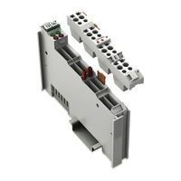
WAGO 753-461/003-000 Manual (56 pages)
2AI Pt 100/RTD 2-Channel Analog Input for RTDs
Brand:
WAGO
| Category:
I/O Systems
| Size: 4.15 MB
Table of Contents
Table of Contents
3
Notes about this Documentation
5
Validity of this Documentation
5
Copyright
5
Table 1: Variants
5
Symbols
7
Number Notation
9
Font Conventions
9
Table 2: Number Notation
9
Table 3: Font Conventions
9
Important Notes
10
Legal Bases
10
Subject to Changes
10
Personnel Qualifications
10
Use of the 750 Series in Compliance with Underlying Provisions
10
Technical Condition of Specified Devices
11
Disposal
11
2.1.4.1.1 Electrical and Electronic Equipment
11
2.1.4.1.2 Packaging
12
Safety Advice (Precautions)
13
Device Description
15
View
17
Figure 1: View
17
Table 4: Legend for Figure "View
17
Connectors
18
Data Contacts/Local Bus
18
Figure 2: Data Contacts
18
Power Jumper Contacts/Field Supply
19
Cage Clamp
19
Figure 3: CAGE CLAMP ® Connectors
19
Table 5: Legend for Figure "CAGE CLAMP ® Connectors
19
Display Elements
21
Figure 4: Display Elements
21
Table 6: Legend for Figure "Display Elements
21
Operating Elements
22
Schematic Diagram
22
Figure 5: Schematic Diagram
22
Technical Data
23
Device Data
23
Power Supply
23
Communication
23
Inputs
23
Table 7: Technical Data - Device
23
Table 8: Technical Data - Power Supply
23
Table 9: Technical Data - Communication
23
Table 10: Technical Data - Inputs (RTD Model 753-461)
23
Climatic Environmental Conditions
24
Connection
24
Table 11: Technical Data - Climatic Environmental Conditions
24
Table 12: Technical Data - Field Wiring
24
Table 13: Technical Data - Data Contacts
24
Approvals
25
Standards and Guidelines
27
Process Image
28
I/O Module with Pt Resistance Sensors
29
Pt100
29
Table 14: I/O Modules with Pt Resistance Sensors
29
Table 15: Process Image, Pt100, with Wire Break Diagnostics
29
753-461/003-000 Configurable I/O Module
30
Table 16: Configurable I/O Module
30
Table 17: Setting Options for the 753-461/003-000 I/O Module
30
Table 18: 753-461/003-000 I/O Module, Offset and Gain Values
31
Table 19: 753-461/003-000 I/O Module, Hardware Matching Input Fields
31
Mounting
32
Mounting Sequence
32
Inserting and Removing Devices
33
Inserting the I/O Module
33
Figure 6: Insert I/O Module (Example)
33
Figure 7: Snap the I/O Module into Place (Example)
33
Removing the I/O Module
34
Figure 8: Removing the I/O Module (Example)
34
I/O Modules with Pluggable Wiring Level (Series 753)
35
Figure 9: Plug and I/O Module
35
Figure 10: Assignment of I/O Module to Plug Using Mini-WSB Tags
35
Coding
36
Figure 11: Attachment of Cable Binders
36
Figure 12: Assembling the Coding Fingers
36
Figure 13: Inserting the Coding Fingers
36
Figure 14: Plugging the Plug into Place
37
Figure 15: "Sure Match" Coding Fingers
37
Plug Removal
38
Figure 16: Pulling the Pull Tab
38
Figure 17: Removing the Plug Without Tools
38
Figure 18: Removing the Plug Using a Screwdriver
38
Connect Devices
39
Connecting a Conductor to the CAGE CLAMP
39
Figure 19: Connecting a Conductor to a CAGE CLAMP
39
Connection Examples
40
RTD, 2-Wire Connection
40
Figure 20: Connection Example: 2 × RTD, 2-Wire Connection
40
RTD, 3-Wire Connection
41
Figure 21: Connection Example: 2 × RTD, 3-Wire Connection
41
Use in Hazardous Environments
42
Marking Configuration Examples
43
Marking for Europe According to ATEX and Iecex
43
Figure 22: Marking Example According to ATEX and Iecex
43
Figure 23: Text Detail - Marking Example According to ATEX and Iecex
43
Table 20: Description of Marking Example According to ATEX and Iecex
44
Figure 24: Marking Example for Approved Ex I I/O Module According to
45
Figure 25: Text Detail - Marking Example for Approved Ex I I/O Module According to ATEX and Iecex
45
Table 21: Description of Marking Example for Approved Ex I I/O Module According to ATEX and Iecex
46
Table 23: Description of Marking Example for Approved Ex I I/O Module
46
Marking for the United States of America (NEC) and Canada (CEC)
47
Figure 26: Marking Example According to NEC
47
Figure 27: Text Detail - Marking Example According to NEC 500
47
Table 22: Description of Marking Example According to NEC 500
47
Figure 28: Text Detail - Marking Example for Approved Ex I I/O Module
48
Figure 29: Text Detail - Marking Example for Approved Ex I I/O Module
48
Table 24: Description of Marking Example for Approved Ex I I/O Modules
48
Figure 30: Text Detail - Marking Example for Approved Ex I I/O Modules
49
Table 25: Description of Marking Example for Approved Ex I I/O Modules
49
Installation Regulations
50
Special Notes Regarding Explosion Protection
50
Special Notes Regarding ANSI/ISA Ex
52
List of Figures
53
List of Tables
54
Advertisement
Advertisement
Related Products
WAGO 753-461
WAGO 753-454
WAGO I/O-SYSTEM 753-456
WAGO 753-452
WAGO 753-431
WAGO 753-482
WAGO WAGO-I/O-SYSTEM 753-661/000-003
WAGO 753-540
WAGO 753-506
WAGO 753-1631
WAGO Categories
I/O Systems
Control Unit
Power Supply
Switch
Controller
More WAGO Manuals
Login
Sign In
OR
Sign in with Facebook
Sign in with Google
Upload manual
Upload from disk
Upload from URL