Altronix AL1042ULADA Installation Manual
Altronix nac power extender installation guide
Hide thumbs
Also See for AL1042ULADA:
- Installation manual (21 pages) ,
- Application manual (8 pages) ,
- Application manual (8 pages)

Subscribe to Our Youtube Channel
Related Manuals for Altronix AL1042ULADA


Summary of Contents for Altronix AL1042ULADA
- Page 1 AL1042ULADA NAC Power Extender Installation Guide (See Application Guide for additional information) Altronix Corp. 140 58th St. Brooklyn, NY Rev. 101413...
-
Page 2: Specifications
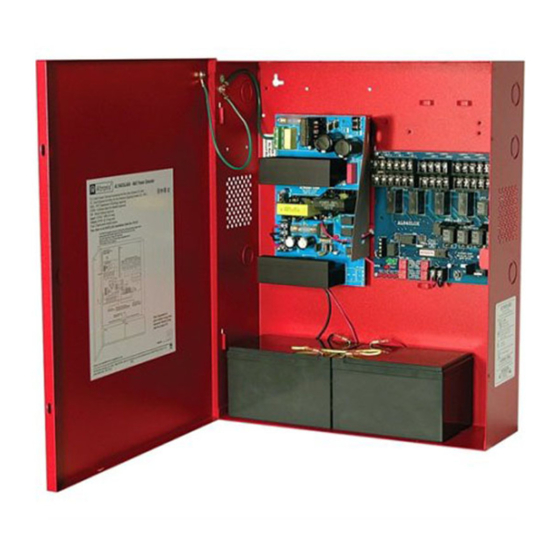
AL1042ULADA - NAC Power Extender Overview: The Altronix AL1042ULADA is an extremely cost effective 10 amp remote power supply/battery charger. It may be con- nected to any 12 or 24 volt Fire Alarm Control Panel (FACP). Primary applications include Notification Appliance Circuit (NAC such as strobes and horns) expansion support to meet ADA requirements. -
Page 3: Power Supply Specifications
4. Connect battery to the terminals marked [+ BAT --] on the Power Supply Board (battery leads included). Note: If batteries being used in your installation do not fit into the AL1042ULADA unit, it is required to install a separate enclosure, UL Listed for appropriate application. Separate battery enclosure is required to have 50 cubic inches of additional open space. - Page 4 Cooper Wheelock. Note: The AL1042ULADA will only synchronize horns, horn/strobes and strobes that contain synchronization capability. Contact signal manufacturer for more detailed info. The same synchronization mode must be selected for all outputs.
- Page 5 “Stand-by Specifications” above for ratings. When loads are connected to the “AUX1” and or “AUX2” outputs during alarm condition, the remaining outputs may, not exceed 10 amp total alarm current. (example: AUX1 = 1 amp, AUX2 = 1 amp, outputs up to 8 amp). AL1042ULADA - 5 -...
-
Page 6: Led Diagnostics
To reset the memory depress the reset button located on the AL842LGK logic board (Fig. 2c, pg. 8). The LED(s) will extinguish. Note: When indicating circuits have restored, trouble memory reset is not required for normal operation. - 6 - AL1042ULADA... - Page 7 NEC Power-Limited Wiring Requirements for AL1042ULADA Models: Power-limited and non power-limited circuit wiring must remain separated in the cabinet. All power-limited circuit wiring must remain at least 0.25” away from any non power-limited circuit wiring. Furthermore, all power-limited circuit wiring and non power-limited circuit wiring must enter and exit the cabinet through different conduits.
-
Page 8: Maintenance
These circuits are used to monitor Detector Detector EOL Powe AC and Bat Fail and will cause a Fire Supervision R - 8 - AL1042ULADA Fire Alarm (Not Supplie simultaneous trouble condition Alarm Control Control to the FACP's IN1 and IN2... -
Page 9: Battery Calculation Worksheet
Current Current For each device use this formula: This column x This column = Equals Current per number of devices. Stand-by: 130mA 130mA AL1042ULADA (Current draw from battery) Alarm: 300mA 300mA AL1042 Current 130mA 300mA Auxiliary Devices Refer to device manual for current ratings. -
Page 10: System Sensor
Appendix A - UL/cUL Listed Compatible Devices for Synchronization A-1 Strobes, Horns and Horn/Strobes Table A-1 below lists Strobes, Horns and Horn/Strobes compatible with AL1042ULADA NAC outputs. Gentex: GCS24CR - UL GCCB24PCR / W - UL GEC24-15/75WR - UL GCS24CW - UL... - Page 11 Appendix A - UL/cUL Listed Compatible Devices for Synchronization (cont’d) A-1 Strobes, Horns and Horn/Strobes Table A-1 below lists Strobes, Horns and Horn/Strobes compatible with AL1042ULADA NAC outputs. Potter/Amseco: CM24CR - UL CSL-1224W-BW - UL/cUL MH-12/24W - UL/cUL SSC8-177R - UL...
-
Page 12: Appendix B - Ul Listed Compatible Devices
STWC-NR - UL Appendix B - UL Listed Compatible Devices B.1 Four (4) Wire Smoke Detectors Table B-1 below lists four (4) wire smoke detectors compatible with AL1042ULADA AUX output and Outputs 1-8 when programmed as AUX. System Sensor Max Stand-by... - Page 13 Notes: AL1042ULADA - 13 -...
- Page 14 Notes: - 14 - AL1042ULADA...
- Page 15 Notes: AL1042ULADA - 15 -...
-
Page 16: Enclosure Dimensions
(114.3mm) (69.85mm) 14.5” (368.3mm) Altronix is not responsible for any typographical errors. 140 58th Street, Brooklyn, New York 11220 USA, 718-567-8181, fax: 718-567-9056 web site: www.altronix.com, e-mail: info@altronix.com, Lifetime Warranty, Made in U.S.A. MEMBER IIAL1042ULADA F13N - 16 - AL1042ULADA...
Need help?
Do you have a question about the AL1042ULADA and is the answer not in the manual?
Questions and answers