
Related Manuals for SMC Networks PF2MC7 Series


Summary of Contents for SMC Networks PF2MC7 Series
- Page 1 No.PF※※-OMZ0002 PRODUCT NAME Digital Flow Switch compatible) MODEL / Series / Product Number PF2MC7##...
-
Page 2: Table Of Contents
Contents Safety Instructions Model Indication and How to Order Summary of Product parts Definition and terminology Mounting and Installation Installation Piping Wiring Outline of Settings [Measurement mode] Flow Setting (set value only) of OUT1 · OUT2 [3 step setting mode] Default settings Simple Setting Mode Function Setting [Function selection mode]... - Page 3 Other Functions Maintenance IO-Link Specifications Outline of IO-Link functions Communication specifications Process data IO-Link parameter setting Troubleshooting Specifications Characteristics data Dimensions No.PF※※-OMZ0002...
-
Page 4: Safety Instructions
Safety Instructions These safety instructions are intended to prevent hazardous situations and/or equipment damage. These instructions indicate the level of potential hazard with the labels of "Caution", "Warning" or "Danger". They are all important notes for safety and must be followed in addition to International Standards (ISO/IEC) , and other safety regulations. - Page 5 Safety Instructions Caution 1.The product is provided for use in manufacturing industries. The product herein described is basically provided for peaceful use in manufacturing industries. If considering using the product in other industries, consult SMC beforehand and exchange specifications or a contract if necessary. If anything is unclear, contact your nearest sales branch.
- Page 6 Operator ♦This operation manual is intended for those who have knowledge of machinery using pneumatic equipment, and have sufficient knowledge of assembly, operation and maintenance of such equipment. Only those persons are allowed to perform assembly, operation and maintenance. ♦Read and understand this operation manual carefully before assembling, operating or providing maintenance to the product.
- Page 7 Caution ■Do not touch the terminals and connectors while the power is on. Otherwise electric shock, malfunction or damage to the product can result. ■After maintenance is complete, perform appropriate functional inspections and leak tests. Stop operation if the equipment does not function properly or there is a leakage of fluid. When leakage occurs from parts other than the piping, the product might be faulty.
- Page 8 ●Product handling ∗Installation •Tighten to the specified tightening torque. If the tightening torque is exceeded the mounting screws, the product may damaged. If the tightening torque is insufficient, the product may be displaced and the mounting screws may come loose. •Ensure that the FG terminal is connected to ground when using a commercially available switch-mode power supply.
- Page 9 ∗Wiring •Do not pull the lead wires. In particular, never lift a product equipped with fitting and piping by holding the lead wires. Otherwise damage to the internal parts can result, causing malfunction or disconnection of the connector. •Avoid repeatedly bending or stretching the lead wire, or placing heavy loads on it. Repeated bending stress or tensile stress can cause damage to the sheath, or breakage of the wires.
- Page 10 ∗Environment •Do not use the product in an environment that is constantly exposed to the splash of water. Otherwise failure or malfunction can result. Take measures such as using a cover. •Do not use the product in an environment where corrosive gases or fluids could be splashed. Otherwise damage to the product and malfunction can result.
- Page 11 ∗Adjustment and Operation •Connect load before turning on the power. •Do not short-circuit the load. Although an error is displayed when the product load is short circuited, excess current may cause damage to the product. •Do not press the setting buttons with a sharp pointed object. This may damage the setting buttons.
-
Page 12: Model Indication And How To Order
Model Indication and How to Order Accessories/Part numbers If an accessory is required, order using the following part number. Part number Description Note ZS-40-A Lead wire with M8 connector Length: 3 m ZS-42-A Bracket With mounting screws for PF2MC7501/7102 (M3 x 5, 2 pcs.) ZS-42-B Bracket With mounting screws for PF2MC7202 (M3 x 5, 2 pcs.) - Page 13 IO-Link compatible product Accessories/Part numbers If an accessory is required, order using the following part number. Part number Description Note ZS-40-A Lead wire with M8 connector Length: 3 m ZS-42-A Bracket With mounting screws for PF2MC7501/7102 (M3 x 5, 2 pcs.) ZS-42-B Bracket With mounting screws for PF2MC7202 (M3 x 5, 2 pcs.)
-
Page 14: Summary Of Product Parts
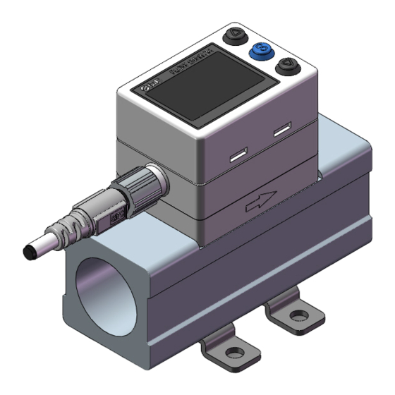
Summary of Product parts Body Connector pin numbers (on the product) DC(+) OUT2/Analogue output/ External input/N.C. DC(-) OUT1 Name Description ∗ Display See below. Connector M8 connector for electrical connections. Lead wire with M8 connector Lead wire for power supply and outputs. Piping port For piping connections. - Page 15 ●IO-Link indicator light operation and display IO-Link status Communication Sub screen display indicator light Status Content ∗1 with master Normal communication status Operate (Reading of measurement value) Correct Start up When communication starts up. Preoperate Version of master and Version does IO-Link IO-Link does not match not match...
-
Page 16: Definition And Terminology
■Definition and terminology Terminology Definition The total amount of fluid that has passed through the device. If an instantaneous Accumulated flow flow of 10 L/min continues for 5 minutes, the accumulated flow will be 5 x 10 = 50 L. Accumulated flow external A function to reset the accumulated flow to "0"... - Page 17 Terminology Definition The resolution of set and display values. Minimum setting unit If the minimum setting unit is 1 L/min, the flow can be displayed in 1 L/min units, i.e. 10, 11, 12. Reference condition for volumetric flow: 101.3 kPa, 0 °C The flow measurement Normal condition (NOR) which is converted at normal atmospheric pressure conditions at 0 °C.
-
Page 18: Mounting And Installation
Mounting and Installation Mounting •Never mount the product in a place where it will be used as a mechanical support. •Mount the product so that the fluid flows in the direction indicated by the arrow on the side of the body. •The monitor with integrated display can be rotated. -
Page 19: Installation
■Installation Bracket mounting •Mount the bracket to the product using the mounting screws (2 pcs.). •Fasten the bracket mounting screws to a torque of 0.5 to 0.7 N•m. •Mount the product with bracket using M4 screws (4 pcs.) or equivalent. •Screw is prepared by customer. - Page 20 Direct mounting •For direct mounting use M3 screws (2 pcs.) or equivalent. •Screws are prepared by customer. •Refer to the dimension drawing (page 99) for the diameter and depth of the mounting screw holes. •Tightening torque is 0.5 to 0.7 N•m. -19- No.PF※※-OMZ0002...
-
Page 21: Piping
■Piping •Never mount the product upside down. •The straight piping length shall be 8 cm or longer. Otherwise, if a straight section of piping is not installed, the accuracy varies by approximately ±2%F.S. Refer to the straight inlet piping length and accuracy graph (page 98). •Avoid sudden changes in the piping size on the IN side of the product. -
Page 22: Wiring
■Wiring Connection •Connections should only be made with the power supply turned off. •Use a separate route for the product wiring and any power or high voltage wiring. Otherwise, malfunction may result due to noise. •Ensure that the FG terminal is connected to ground when using a commercially available switch-mode power supply. - Page 23 Internal circuit and wiring examples PF2MC7###-##-A#-### NPN (2 outputs) type Maximum applied voltage: 28 V Maximum load current: 80 mA Internal voltage drop: 1.5 V or less PF2MC7###-##-C#-### NPN (1 output) + Analogue (1 to 5 V) output type PF2MC7###-##-D#-### NPN (1 output) + Analogue (4 to 20 mA) output type Maximum applied voltage: 28 V Maximum load current: 80 mA...
- Page 24 PF2MC7###-##-B#-### PNP (2 outputs) type Maximum load current: 80 mA Internal voltage drop: 1.5 V or less PF2MC7###-##-E#-### PNP (1 output) + Analogue (1 to 5 V) output type PF2MC7###-##-F#-### PNP (1 output) + Analogue (4 to 20 mA) output type Maximum load current: 80 mA Internal voltage drop: 1.5 V or less E: Analogue output: 1 to 5 V...
- Page 25 Example of wiring for accumulated pulse output PF2MC7###-##-A/B/C/D/E/F#-### NPN (2 outputs) type PNP (2 outputs) type -24- No.PF※※-OMZ0002...
- Page 26 PF2MC7###-##-L#-### NPN type Maximum applied voltage: 30 V Maximum load current: 80 mA Internal voltage drop: 1.5 V or less PF2MC7###-##-L2#-### NPN type Maximum applied voltage: 30 V Maximum load current: 80 mA Internal voltage drop: 1.5 V or less PF2MC7###-##-L3/L4#-### NPN type Maximum applied voltage: 30 V...
- Page 27 PF2MC7###-##-L2#-### NPN + External input type Maximum applied voltage: 30 V Maximum load current: 80 mA Internal voltage drop: 1.5 V or less External input: Input voltage 0.4 V or less (reed or solid state input) for 30 msec. or longer PF2MC7###-##-L#-### PNP type Maximum load current: 80 mA...
- Page 28 PF2MC7###-##-L3/L4#-### PNP type Maximum load current: 80 mA Internal voltage drop: 1.5 V or less L3: Analogue output: 1 to 5 V or 0 to 10 V Output impedance: 1 kΩ L4: Analogue output: 4 to 20 mA Maximum load impedance: 600 Ω Minimum load impedance: 50 Ω...
- Page 29 Example of wiring for accumulated pulse output NPN output type PF2MC7###-##-L#-### NPN 2 outputs + Analogue output type PF2MC7###-##-L2#-### NPN (1 output) + Analogue output type PF2MC7###-##-L3/L4#-### PNP output type PF2MC7###-##-B#-### PNP 2 outputs PF2MC7###-##-L2#-### PNP (1 output) + Analogue output type PF2MC7###-##-L3/L4#-### -28- No.PF※※-OMZ0002...
-
Page 30: Outline Of Settings [Measurement Mode]
Outline of Settings [Measurement mode] Power is supplied The output will not operate for 3 seconds after supplying power. The identification code of the product is displayed. [Measurement mode] Measurement mode is the condition where the flow is detected and displayed, and the switch function is operating. -
Page 31: Flow Setting (Set Value Only) Of Out1 · Out2 [3 Step Setting Mode]
Flow Setting (set value only) of OUT1 · OUT2 [3 step setting mode] 3 step setting mode In this mode, only the set values can be input, in just 3 steps. Use this mode if the product is to be used straight away, after changing only the set values. ■Default settings When the flow exceeds the set value [P_1], the switch will be turned ON. - Page 32 <Operation> 1. Press the SET button in measurement mode to display set values. (The item to be changed is displayed on the sub display) Set value on the right side of the sub screen flashes. 2. Press the UP or DOWN button to change the set value. The UP button is to increase and the DOWN button is to decrease the set value.
-
Page 33: Simple Setting Mode
Simple Setting Mode <Operation> [Simple setting mode (hysteresis mode) In the simple setting mode, the set value and hysteresis can be changed while checking the current flow value (main screen). (1) Press and hold the SET button for 1 to 3 seconds in measurement mode. [SEt] is displayed on the main screen. -
Page 34: Function Setting [Function Selection Mode]
Function Setting [Function selection mode] Function selection mode In this mode, each function setting can be changed separately. In measurement mode, press the SET button between 3 and 5 seconds, to display [F 0]. Press the UP or DOWN button to select the function to be changed. Press the SET button for 2 seconds or longer in function selection mode to return to measurement mode. -
Page 35: Default Settings
■Default settings Item (Main display) Default settings (Sub display) Page [rEF ] Reference condition [ Std] Standard condition ∗1 [Unit] Unit selection function L] L/min [F 0] Page Refer to the default settings of the switch output [NorP] SW output PNP/NPN setting PNP/NPN on page 35. - Page 36 Default settings of switch output PNP/NPN Selection of the switch output (PNP or NPN) is arbitrary, but the default setting varies depending on the product code when ordered. (Refer to the table below) Default setting Model (Output specification) OUT1 OUT2 Analogue 1 to 5 V Analogue 4 to 20 mA Analogue 1 to 5 V...
-
Page 37: F0 Selection Of Reference Condition, Unit Selection Function, Switch Output Specifications
■[F 0] Selection of reference condition, unit selection function, switch output specifications. Reference condition Standard condition or normal condition can be selected. Standard condition (ANR) and normal condition (NOR) are defined as follows: •Standard condition (ANR): 101.3 kPa, 20 °C •Normal condition (NOR): 101.3 kPa, 0 °C Unit selection function ∗... - Page 38 Switching setting of switch output NPN/PNP specifications The switch output of this product can be switched to PNP or NPN output in accordance with the user device construction. Press the UP or DOWN button to select switch output specification. Press the SET button to set. Press the SET button to set.
- Page 39 Flow specification when [CF] is selected during the unit selection function. Model PF2MC7501 PF2MC7102 PF2MC7202 Rated flow range 0.2 to 17.7 cfm 0.4 to 35.3 cfm 0.8 to 70.6 cfm Instantaneous 0.2 to 18.5 cfm 0.4 to 37.1 cfm 0.8 to 74.2 cfm flow Set flow rate range...
-
Page 40: F1 Setting Of Out1
■[F 1] Setting of OUT1 Set the output mode of OUT1. ●Switch output operation list Select the operation required from the table below. Characters in ( ) are for OUT2. Normal output Reversed output Hysteresis mode Window comparator mode Accumulated output mode (Increment) Accumulated... - Page 41 <Flowchart of functions> 1. Selection of output mode Window Accumulated Hysteresis Pulse output Error output Output OFF comparator output Wind 2. Setting of switch operation 1_P/1_n (page 41) (Selection of display colour) Setting of dEC1 dEC2 (page 45) 3. Input of set values Setting of Setting of P1L/n1L...
- Page 42 <Operation> Press the UP or DOWN button in function selection mode to display [F 1]. Press the SET button. Move on to output mode setting. Output mode setting Press the UP or DOWN button to select the output mode. ∗: When the accumulated pulse output is selected, the output display (Indicator LED) will turn off. Press the SET button to set.
- Page 43 Hysteresis setting The sub screen (right side) displays the hysteresis value. Change it with the UP and DOWN buttons. ∗: The set value and hysteresis range will be limited depending on the values. Press the SET button to set. Move on to delay time setting. Delay time setting The sub screen (right side) displays the delay time value.
- Page 44 Input of set values b, When window comparator output mode is selected. The sub screen (right side) displays the set value. Change it with the UP and DOWN buttons. (When reversed output is selected, the sub screen (left side) displays [n1L].) Press the SET button to set.
- Page 45 Input of set values c, When accumulated output mode is selected. Selection of accumulated increment or decrement. Press the UP or DOWN button to select. Press the SET button to set. Move on to the input of set values. The sub screen (right side) displays the set value. Change it with the UP and DOWN buttons.
- Page 46 ●Setting range of the accumulated flow output The accumulated output setting range is displayed by the set value of the 4 digits and the units. Set the value by key operation in the sub display. The upper 4 digits of the value is displayed by shifting of the digit.
-
Page 47: F2 Setting Of Out2
■[F 2] Setting of OUT2 The output mode of OUT2 can be selected. ∗: If the product with no switch output specification is used, "---" is displayed and this function is not available. <Flowchart of functions> 1. Selection of output mode Window Accumulated Hysteresis... - Page 48 <Operation> Press the UP or DOWN button in function selection mode to display [F 2]. Press the SET button. Move on to output mode setting. Output mode setting Press the UP or DOWN button to select the output mode. ∗: When the accumulated pulse output is selected, the output display (Indicator LED) will turn off. Press the SET button to set.
- Page 49 Hysteresis setting The sub screen (right side) displays the hysteresis value. Change it with the UP and DOWN buttons. ∗: The set value and hysteresis range will be limited depending on the values. Press the SET button to set. Move on to delay time setting. Delay time setting The sub screen (right side) displays the delay time value.
- Page 50 Input of set values b, When window comparator output mode is selected. The sub screen (right side) displays the set value. Change it with the UP and DOWN buttons. (When reversed output is selected, the sub screen (left side) displays [n2L].) Press the SET button to set.
- Page 51 Input of set values b, When window comparator output mode is selected. Selection of accumulated increment or decrement. Press the UP or DOWN button to select. Press the SET button to set. Move on to the input of set values. The sub screen (right side) displays the set value.
- Page 52 Selection of display colour The display colour (main screen) can be selected depending on the switch output condition. ∗: The display colour setting is linked to the [F 1] OUT1 setting. Press the SET button to set. Return to function selection mode. [F 2] Setting of OUT2 is completed.
-
Page 53: F3 Digital Filter Setting
■[F 3] Digital filter setting Set the digital filter. Output chattering or flicker in the measurement mode display can be reduced by setting the digital filter. <Operation> Press the UP or DOWN button in function selection mode to display [F 3]. Press the SET button. -
Page 54: F10 Sub Screen Setting
■[F10] Sub screen setting Set the sub screen display. Detailed contents are shown in the pages from 54. <Operation> Press the UP or DOWN button in function selection mode to display [F10]. Press the SET button. Move on to sub screen setting. Sub screen setting Press the UP or DOWN button to select the display style for the sub screen. - Page 55 <Sub screen display> The following display items and values can be displayed on the sub screen. The displayed item varies depending on the setting of the output mode. Select the displayed items by pressing the UP or DOWN button in measurement mode. ∗: Sub screen display (for 500 L range) OUT1 setting ∗: The display setting for the temperature HYS and temperature Win will be displayed when a temperature sensor is connected.
- Page 56 Bottom value display Peak value display -55- No.PF※※-OMZ0002...
- Page 57 Switch output/communication mode display (for IO-Link compatible products only) Item Content Condition SIO mode SIO mode or WakeUp Strt StartUp mode StartUp PreOperate mode Pre Operate Operate mode Operate Data storage LOC mode Data storage LOC and SIO mode When the setting of [F10] is other than [dEF] OUT1 setting -56- No.PF※※-OMZ0002...
- Page 58 •Peak/Bottom value The maximum flow (peak) and minimum flow (bottom) flow from when the power is supplied to this moment is detected and updated. Peak and bottom values can be reset by pressing the SET and DOWN buttons simultaneously for 1 second.
- Page 59 •Display of accumulated value The power display (Value×10 power) and upper digit - lower digit are displayed alternately. The sub screen always displays power. When the DOWN button is pressed for 1 second on the accumulated value display screen, the display will be switched alternately.
-
Page 60: F14 Zero-Cut Setting
■[F14] Zero-cut setting A function to force the display to zero to remove flickering at the lower measurement range. <Operation> Press the UP or DOWN button in function selection mode to display [F14]. Press the SET button. Move on to the setting of the zero cut-off display function. Setting of zero cut-off function Press the UP or DOWN button to select the zero cut-off value. -
Page 61: F20 Setting Of External Input
■[F20] Setting of external input This function is available when the model includes the external input function. The accumulated flow, peak value and bottom value can be reset remotely. ∗: When using a model without external input function, this setting is not available and [---] will be displayed. •Accumulated flow external reset: A function to reset the accumulated flow value when an external input signal is applied. -
Page 62: F22 Analogue Output Setting
■[F22] Analogue output setting This function is available when the model includes the analogue output. Change the analogue output set value and analogue free range. ∗ When using a model without analogue outputs, this setting is not available and [- - -] will be displayed. <Operation>... -
Page 63: F30 Accumulated Flow Value Hold Setting
■[F30] Accumulated flow value hold setting Select the setting in which the accumulated flow measurement value is stored to the internal memory. The default setting is not to store the accumulated flow when the power supply is turned off. This function enables the accumulated flow value to be stored in permanent memory every 2 or 5 minutes. The internal memory life varies depending on the number of times that the memory device can be accessed, so this must be taken into account before use. -
Page 64: F80 Display Off Mode Setting
■[F80] Display OFF mode setting Select the display ON/OFF mode. With this function, the display will change to OFF mode when no button operations are performed for 30 seconds. During the display OFF mode operation, the under bars on the right side of the sub screen will flash for 3 digits. -
Page 65: F81 Setting Of Security Code
■[F81] Setting of security code The Security code can be changed during key lock mode. <Operation> Press the UP or DOWN button in function selection mode to display [F81]. Press the SET button. Move on to security code. Security code Press the UP or DOWN button to select the setting of security code. - Page 66 Security code changing Press the UP or DOWN button to input the ∗ changed security code on the main screen. For instructions on how to enter the security code, refer to "How to input and change the security code" on page 75. After entry, the changed security code will flash by pressing the SET button for 1 second.
-
Page 67: F90 Setting Of All Function
■[F90] Setting of all functions All functions can be set one after the other, without having to select each one separately from the function selection mode. <Operation> Press the UP or DOWN button in function selection mode to display [F90]. Press the SET button. -
Page 68: F96 Check Of Input Signal
■[F96] Check of external input signal When the external input is selected, ON / OFF of the input signal can be checked. ∗: When the analogue output is selected, ON/OFF of the input signal cannot be checked. <Operation> Press the UP or DOWN button in function selection mode to display [F96]. Press the SET button. -
Page 69: F98 Setting Of Output Check
■[F98] Setting of output check The operation of the output can be checked by switching the output ON/OFF by pressing a button, without the need for a flow of fluid. <Operation> Press the UP or DOWN button in function selection mode to display [F98]. Press the SET button. - Page 70 Analogue output check Press the UP or DOWN button to select analogue output check. ∗: When 0-10V is selected for voltage output type, [ 0.0] ⇔ [ 10.0] is displayed. ∗: For current output type, [ 4] ⇔ [ 20] is displayed. When the product is used in When the product is used in SIO mode...
- Page 71 PD diagnostic bit (error) check Press the UP or DOWN button to select diagnostic bit (error) check. ∗: This function is available with IO-Link communication. ∗: Refer to page for details of the diagnostic information. Move on to PD diagnostic Press the SET button to set.
-
Page 72: F99 Reset To Default Settings Other Functions
■[F99] Reset to default settings If the product settings are uncertain, the default values can be restored. <Operation> Press the UP or DOWN button in function selection mode to display [F99]. Press the SET button. Move on to reset to default settings. Reset to default settings Press the UP or DOWN button to display [ON], then press the SET and DOWN buttons simultaneously for 5 second or longer. -
Page 73: Other Functions
Other Functions ○Snap shot function The current flow/temperature value can be stored to the switch output ON/OFF set point. When the items of sub screen (left side) below are selected in 3 step setting mode, simple setting mode or function selection mode ([F 1] Setting of OUT1, [F 2] Setting of OUT2), by pressing the UP and DOWN buttons simultaneously for 1 second or longer, the value of the sub screen (right side) shows [- - -], and then values corresponding to the current flow are automatically displayed. - Page 74 ○Key-lock function The key-lock function is used to prevent errors occurring due to unintentional changes of the set values. If the SET button is pressed while the keys are locked, [LoC] is displayed on the sub screen (left side) for approximately 1 second.
- Page 75 •Unlocking (1) Press the SET button for 5 seconds or longer in measurement mode. When [oPE] is displayed on the main screen, release the button. The current setting [LoC] or [UnLoC] will be displayed on the sub screen. (2) Select the un-locking [UnLoC] with UP or DOWN button. Setting is recognized by pressing the SET button, then security code is required.
- Page 76 ●How to input and change the security code The left most digit starts flashing. Press the UP or DOWN button to select a value. Press the SET button to make the next digit to the right flash. (If the SET button is pressed at the last digit, the first digit will start flashing.) After the setting is complete, Press and hold the SET button for 1 second or longer.
-
Page 77: Maintenance
Maintenance How to reset the product after a power cut or when the power has been unexpectedly removed The settings of the product are retained from before the power cut or de-energizing. The output condition also recovers to that before power cut or de-energizing, but may change depending on the operating environment. -
Page 78: Process Data
■Process data Process data is the data which is exchanged periodically between the master and device. This product process data consists of switch output status, error diagnostics, flow measurement value and temperature measurement value. (Refer to the table below.) Bit offset Item Notes OUT1 output... - Page 79 ○Unit specification and flow measurement value (PD) Flow value PD value Flow Display/settable Display/settable Series Unit Rated flow range Rated flow range range range range Min. Max. Min. Max. 500 L 5 to -25 to L/min 1000 L 10 to 1000 -50 to 1050 2000 L 20 to 2000...
- Page 80 = 625 [L/min] (2) Conversion from the flow measurement value to the process data (For PF2MC7 series, unit L/min, flow range 1000 L and Pr = 800 [L/min]) (PD) = (Pr - b) / a = [800 - 0] / 0.25...
-
Page 81: Io-Link Parameter Setting
■IO-Link parameter setting ○IODD file IODD (I/O Device Description) is a definition file which provides all properties and parameters required for establishing functions and communication of the device. IODD includes the main IODD file and a set of image files such as vendor logo, device picture and device icon. - Page 82 ●ISDU parameters Index Access Parameters Initial value Remarks ∗1 index (dec) 0x0002 Refer to "System command" on System command page 81. 0x000C Refer to "Device access lock 0x0000 Device access lock (12) parameter" on page 82. 0x0010 SMC Corporation Vendor name (16) 0x0011 www.smcworld.com...
- Page 83 ●Device access lock parameter (index 12) The contents are as follows. Data type: 16 bit Record Value Contents Key lock release, DS unlock (Initial value) Key lock release, DS lock Key lock, DS unlock Key lock, DS lock [Key lock] This function prevents the user from physically changing the setting of the flow switch (button operation is not accepted).
- Page 84 ●Product individual parameters Data Data Index Access Initial ∗4 Parameter type storage Set value Remarks ∗1 index value ∗2 ∗3 When the unit selection function is 0: L (L/min) Unit not included, 1000 0x03E8 1: Ft (cfm) (Unit setting) a read/write to an un-selectable item is rejected.
- Page 85 ●Product individual parameters (continued) Data Data Index Access Initial ∗4 Parameter type storage Set value Remarks ∗1 index value ∗2 ∗3 Setting range AC1_L Setting of OUT1 mantissa 0 to 9999 (Mantissa L) Unit: when “L” is selected 1300 0x0514 ∗5 Setting range AC1_L...
- Page 86 ●Product individual parameters (continued) Data Data Index Access Initial ∗4 Parameter type storage Set value Remarks ∗1 index value ∗2 ∗3 0: dEF (Default) 1: LinE (Line name) (Setting of lower level 2: oFF (Display OFF) screen) 2000 0x07D0 Refer to "Selection of (During dEF setting display items"...
- Page 87 ●Product individual parameters (continued) Data Data Index Access Initial ∗4 Parameter type storage Set value Remarks ∗1 index value ∗2 ∗3 0: Normal output The PD becomes 1 when a fixed 7000 0x1B58 OUT Test 1: Fixed output output has been received. 0: Measured value 16: OUT1 17: OUT2...
- Page 88 [dEF Selection of display items during standard setting] Value Setting content Supplemental information HYS mode set value HYS mode hysteresis Wind mode lower side set value Wind mode upper side set value OUT1 Wind mode hysteresis Accumulated output mode Accumulated pluse output mode Err mode oFF mode When the value which does not match the OUT∗...
- Page 89 [Line name communication data] Value (16 hex number) 7seg 11seg Value (16 hex number) 7seg 11seg Value (16 hex number) 7seg 11seg Supplementary When is displayed, a reject response will be sent. information -88- No.PF※※-OMZ0002...
-
Page 90: Troubleshooting
Troubleshooting If an operation failure of the product occurs, please confirm the cause of the failure from the following table. If a cause applicable to the failure cannot be identified and normal operation can be recovered by replacement with a new product, this indicates that the product itself was faulty. Problems with the product may be due to the operating environment (installation etc). - Page 91 Fault Possible cause Countermeasures Incorrect wiring. Correct the wiring. No output. Loose connector. Connect the connector. Install a filter or mist separator on the IN side if there is a risk of foreign matter entering the product. Foreign matter in the sensor. If there is foreign matter on the mesh, remove it completely, taking care not to damage the product.
- Page 92 ○Troubleshooting list (IO-Link communication) Problem possible Problem Investigation method Countermeasures causes Description Check the connection of the incorrect wiring Correct the cable wiring. connector. IO-Link indicator light Power supply Check the power supply Supply 18 to 30 VDC to the : OFF error from the voltage from the IO-Link...
- Page 93 ○Error indication function This function is to display error location and content when a problem or error has occurred. Error name Error display Description Measures A load current applied to the switch OUT1 output has exceeded the max. value over current error (OUT1).
-
Page 94: Specifications
Specifications Model PF2MC7501 PF2MC7102 PF2MC7202 Air, N Applicable fluid (Air quality: ISO8573-1 1.1.2 to 1.6.2) Fluid temperature range 0 to 50 Detecting method Heating type sensor Rated flow range 5 to 500 L/min 10 to 1000 L/min 20 to 2000 L/min Instantaneous flow 5 to 525 L/min 10 to 1050 L/min... - Page 95 Model PF2MC7501 PF2MC7102 PF2MC7202 Voltage output: 1 to 5 VDC, 0 to 10 VDC (only when the power supply voltage is 24 VDC) Output type Current output: 4 to 20 mA (Refer to analogue output graph) Output impedance approx. 1 kΩ Voltage output Maxi.
- Page 96 Model PF2MC7501 PF2MC7102 PF2MC7202 IO-Link type Device IO-Link version V1.1 Communication speed COM2 (38.4 kbps) Min. cycle time 3.4 ms Process data length Input Data: 4 byte, Output Data: 0 byte On request data communication Available Data storage function Available Event function Available Vendor ID...
-
Page 97: Characteristics Data
■Characteristics data ●Flow rate/ Analogue output 0 L/min 0 L/min Voltage output Voltage output 1.04 V 0.1 V 10 V ∗1 ∗1, ∗2 (1 to 5 V) (0 to 10 V) ∗1 Current output 4 mA 4.16 mA 20 mA Models Minimum value of rated flow range Maximum value of rated flow range... - Page 98 ●Pressure loss PF2MC7501 (500 L/min) PF2MC7102 (1000 L/min) PF2MC7202 (2000 L/min) -97- No.PF※※-OMZ0002...
- Page 99 ●Straight inlet piping length and accuracy (reference value) •The smaller the piping size, the more the product is affected by the straight piping length. •The smaller the flow rate, the less the product is affected by the straight piping length. •The straight piping length shall be 8 cm or longer in order to maintain ±3%F.S.
-
Page 100: Dimensions
■Dimensions PF2MC7501/7102/7202 Symbol Piping port size Model PF2MC7501/7102 Rc1/2, NPT1/2 60.6 41.2 13.6 PF2MC7202 Rc3/4, NPT3/4, G3/4 66.1 46.7 17.5 16.8 PF2MC7501/7102 G1/2 60.6 41.2 13.6 Bracket dimensions Symbol Model PF2MC7501/7102 PF2MC7202 -99- No.PF※※-OMZ0002... - Page 101 Lead wire with M8 connector (ZS-40-A) M12-M8 conversion lead wire (ZS-40-M12M8-A) -100- No.PF※※-OMZ0002...
- Page 102 Revision history 4-14-1, Sotokanda, Chiyoda-ku, Tokyo 101-0021 JAPAN Tel: + 81 3 5207 8249 Fax: +81 3 5298 5362 https://www.smcworld.com Note: Specifications are subject to change without prior notice and any obligation on the part of the manufacturer. © 2021 SMC Corporation All Rights Reserved No.PF※※-OMZ0002...
Need help?
Do you have a question about the PF2MC7 Series and is the answer not in the manual?
Questions and answers