Table of Contents
Advertisement
Advertisement
Table of Contents

Related Manuals for SMC Networks PF3W7 Series


Summary of Contents for SMC Networks PF3W7 Series
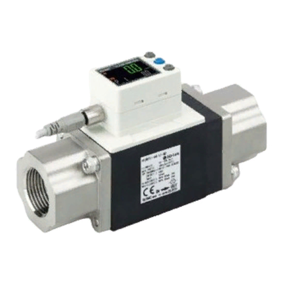
- Page 1 No.PF##-OMM0005 Digital Flow Switch PRODUCT NAME PF3W7## MODEL/ Series...
-
Page 2: Table Of Contents
Table of Contents Safety Instructions Model Indication and How to Order Names and Functions of Product Definition and terminology Mounting and Installation Installation Piping Wiring Flow (Temperature) Setting Setting of Functions Default settings F1 Setting of OUT1 F2 Setting of OUT2 F3 Response time setting F10 Selection of sub screen F20 Setting of external input... -
Page 3: Safety Instructions
Safety Instructions These safety instructions are intended to prevent hazardous situations and/or equipment damage. These instructions indicate the level of potential hazard with the labels of "Caution", "Warning" or "Danger". They are all important notes for safety and must be followed in addition to International standards (ISO/IEC), Japan Industrial Standards (JIS) and other safety regulations *1) ISO 4414: Pneumatic fluid power - - General rules relating to systems. - Page 4 Caution 1. The product is provided for use in manufacturing industries. The product herein described is basically provided for peaceful use in manufacturing industries. If considering using the product in other industries, consult SMC beforehand and exchange specifications or a contract if necessary. If anything is unclear, contact your nearest sales branch.
- Page 5 Operator ♦This operation manual has been written for those who have knowledge of machinery and apparatus that use pneumatic equipment and have full knowledge of assembly, operation and maintenance of such equipment. ♦Please read this operation manual carefully and understand it before assembling, operating or providing maintenance to the product.
- Page 6 ■NOTE ○Follow the instructions given below when designing, selecting and handling the product. ●The instructions on design and selection (installation, wiring, environment, adjustment, operation, described below must also be followed. maintenance, etc.) ∗Product specifications •The direct current power supply to be used should be UL approved as follows. Circuit (of class 2) which is of maximum 30 Vrms (42.4 V peak) or less, with UL 1310 class 2 power supply unit or UL 1585 class 2 transformer.
- Page 7 ●Product handling ∗Installation •Tighten to the specified tightening torque. If the tightening torque is exceeded the mounting screws, brackets and the product can be broken. Insufficient torque can cause displacement of the product from its proper position and the looseness of the mounting screws. (Refer to "Mounting and Installation"...
- Page 8 •Do not route wires and cables together with power or high voltage cables. Otherwise the product can malfunction due to interference of noise and surge voltage from power and high voltage cables to the signal line. Route the wires (piping) of the product separately from power or high voltage cables. •Confirm proper insulation of wiring.
- Page 9 ∗Adjustment and Operation •Connect a load before turning the power supply on. If switched ON with no load, over current may flow, causing the product to break instantly. •Do not short-circuit the load. Although error is displayed when the product load has a short circuit, generated over current lead to cause the damage of the product.
-
Page 10: Model Indication And How To Order
Model Indication and How to Order No.PF##-OMM0005... - Page 11 Lead wire With lead wire and M8 connector Without lead wire, with M8 connector Bracket No bracket With bracket Options/Part number If an option is required separately, order using the following part numbers. Option Part number Remarks ZS-40-K With 4 tapping screws for PF3W704/720 (3x10) Bracket ZS-40-L With 4 tapping screws for PF3W740 (3x10)
-
Page 12: Names And Functions Of Product
Names and Functions of Product Body Display Description Item Main screen Displays the flow, the status of setting mode and error code. Displays the accumulated flow, set value, peak/bottom value, fluid temperature and Sub screen line names. In the setting mode, the set status is displayed. Output display Displays the output status of OUT1 and OUT2. -
Page 13: Definition And Terminology
■Definition and terminology Terms Meaning The total amount of fluid that has passed through the device. If an instantaneous flow Accumulated flow of 10 L/min lasts for 5 minutes, the accumulated flow will be 5×10=50 L. Accumulated flow A function to reset the accumulated flow to zero by using an external signal. external reset Accumulated pulse A type of output where a pulse is generated every time a predefined accumulated flow... - Page 14 Terms Meaning Part in contact with A part that comes into physical contact with the fluid. fluid (wetted part) Pressure Change in the display value and analog output when the fluid pressure is changed. characteristics Pressure limit that if exceeded will result in mechanical and/or electrical damage to the Proof pressure product.
-
Page 15: Mounting And Installation
Mounting and Installation Mounting •Use the product within the specified operating pressure range. •Use the product within the operating temperature range. •Proof pressure is 1.5 MPa. •Never mount the product in such a way that it could be used as a support during piping. •Mount the product so that the fluid flows in the direction indicated by the arrow on the side of the body. -
Page 16: Installation
■Installation Bracket mounting Attach the bracket using the mounting screws supplied (equivalent to M4 x 4 pcs.). The thickness of the bracket plate is approx. 1.5 mm. Refer to the outer dimensions drawing (page 67) for mounting hole machining sizes. Direct mounting Mount using the self tapping screws (nominal size: 3.0 x 4 pcs.) for... -
Page 17: Piping
■Piping When connecting piping to the product, a spanner should only be used on the metal part (piping attachment). Using a spanner on other parts may damage the product. In particular, do not let the spanner come into contact with the M8 connector. The connector can be easily damaged. -
Page 18: Wiring
■Wiring Internal Circuit and Wiring NPN 2 Output type PNP 2 Output type PF3W7 -A(T)- PF3W7 -B(T)- Max. 28 V, 80 mA Max. 80 mA Internal voltage drop 1 V max. Internal voltage drop 1.5 V max. NPN + Analog output type PNP + Analog output type PF3W7 -C(T)-... - Page 19 Example of wiring for accumulated pulse output NPN 2 output type PF3W7 -A(T)- NPN + Analog output type PF3W7 -C(T)- PF3W7 -D(T)- NPN + External input type PF3W7 PNP 2 output type PF3W7 -B(T)- PNP + Analog output type PF3W7 -E(T)- PF3W7 -F(T)-...
-
Page 20: Flow (Temperature) Setting
Flow (Temperature) Setting Measurement mode The condition where the flow is detected and displayed, and the switch function is operating. This is the basic operating mode; other modes should be selected for set-point and other function setting changes. Set ON and OFF points of the Flow switch. Switch operation When the flow exceeds the set value, the Flow switch will be turned on. - Page 21 <Operation> 1. Press the button in measurement mode to display set values. 2. [P_1] or [n_1] and the set value are displayed alternately. 3. Press the button to change the set value. button is to increase and the button is to decrease the set value. •Press the button once to increase by one digit, press and hold to continuously increase.
-
Page 22: Setting Of Functions
Setting of Functions Function selection mode In measurement mode, when the button is pressed for 2 seconds or longer, [F 1] is displayed. This [F ] indicates the mode for changing each functional setting. Press the button for 2 seconds or longer to return to measurement mode. The function number is ∗: The sub screen increased and decreased... - Page 23 ●Other parameter setting Item Page Default setting / With the temperature sensor in parenthesis [F 3] Response time setting See page 37 1 s. [F10] Selection of sub screen See page 38 Display of set value (Display of fluid temperature) [F20] Setting of external input See page 42 Accumulated flow external reset...
-
Page 24: F1 Setting Of Out1
■[F 1] Setting of OUT1 The output mode of OUT1 can be selected. <Flowchart of functions> 1. Selection of output mode Window Hysteresis Accumulated Accumulated comparator mode output pulse mode ACCUMU 2. Setting of reversed output 1_P/1_N (Page 24) ∗ 3. - Page 25 <Operation> 1. Selection of output mode Press the button in function selection mode to display [F 1] on the main screen. The sub screen alternately displays [oUt1] and the currently set output mode. Press the button. screen Press the button to select the desired output mode.
- Page 26 3. Input of set values a. When hysteresis output mode is selected. The sub screen displays the set value. Change it with the buttons. (When reversed output is selected, the main screen displays [n_1].) Press the button to confirm. Move on to the setting of hysteresis. The sub screen displays the hysteresis.
- Page 27 c. When accumulated output mode is selected. Selection of accumulated increment or decrement screen Press the button to select the desired output mode. Press the button to confirm. Move on to the input of set values. When accumulated increment is selected. When accumulated decrement is selected.
- Page 28 Setting of the first Setting of the latter The leftmost digit of the set 3 digits 6 digits value will start flashing. The required accumulated value should be input one digit at a time. Press the buttons to change the value. Press the button to select the Press the...
- Page 29 4. Selection of display color Display color can be set to change depending upon the status of OUT1. screen Press the button to select the desired display color. Press the button to confirm. Return to function selection mode. 5. Complete [F 1] Setting of OUT1 complete -28- No.PF##-OMM0005...
- Page 30 ○List of output modes ∗: If hysteresis or window comparator mode is selected and there is an unstable flow condition (due to fluid pulsation, for example), unstable output operation can result. In such situations, keep sufficient margin between the set values and confirm that the output operation stabilizes. ∗: When the accumulated pulse output is selected, the output display will turn off.
- Page 31 -30- No.PF##-OMM0005...
-
Page 32: F2 Setting Of Out2
■[F 2] Setting of OUT2 The output mode of OUT2 can be selected. The display color is defined by OUT1 and cannot be changed with any OUT2 settings. <Flowchart of functions> With temperature 1. - Page 33 <Operation> 1. Selection of output mode Press the button in function selection mode to display [F 2] on the main screen. The sub screen displays [oUt2] and the currently set output mode alternately. ∗: If OUT2 is not provided, the display will be [---]. Press the button.
- Page 34 3. Input of set values a. When hysteresis output mode is selected. The sub screen displays the set value. Change it with the buttons. (When reversed output is selected, the main screen displays [n_2].) Press the button to confirm. Move on to the setting of hysteresis. The sub screen displays the hysteresis.
- Page 35 c. When accumulated output mode is selected. Selection of accumulated increment or decrement The setting of Add/dEC is linked to the setting of OUT1, and can not be selected. (Page 26) When accumulated increment is selected. When accumulated decrement is selected. The sub screen displays the set The sub screen displays the set value.
- Page 36 d. When hysteresis mode for fluid temperature is selected The sub screen displays the set value. Change it with the buttons. (When normal output is selected, the main screen displays [ tP].) Press the button to confirm. Move on to the setting of hysteresis. The sub screen displays the set value.
- Page 37 ○List of output modes for fluid temperature -36- No.PF##-OMM0005...
-
Page 38: F3 Response Time Setting
■[F 3] Response time setting The response time of the switch output can be set. Appropriate setting of the response time can prevent the switch output from chattering. <Operation> Press the button in function selection mode to display [F 3] on the main screen. The sub screen alternately displays [RES] and the current set value. -
Page 39: F10 Selection Of Sub Screen
■[F10] Selection of sub screen The display shown on the sub screen during measurement mode can be set. •Switch point value display: Displays the set value for switch point of OUT1. (Neither the switch point nor accumulated values of OUT2 can be displayed.) •Accumulated value display: Displays the accumulated value of OUT1. - Page 40 <Example of display of sub screen> -39- No.PF##-OMM0005...
- Page 41 <Example of display of sub screen (continued)> -40- No.PF##-OMM0005...
- Page 42 <Example of display of sub screen (continued)> The maximum (peak) and minimum (bottom) flow from when the power is supplied to this moment is detected and updated. •Pressing the buttons for 1 second clears the peak and bottom values. •If the external input is available, the values can also be reset by external input. •Refer to [F20] Setting of external input on page 42.) The name of the piping line in which the product is installed can be displayed.
-
Page 43: F20 Setting Of External Input
■[F20] Setting of external input This function can be used only when the optional external input is present. The accumulated value, peak value and bottom value can be reset remotely. Accumulated value external reset: A function to reset the accumulated value when an input signal is applied. -
Page 44: F22 Setting Of Analog Output
■[F22] Setting of analog output This function can be used only when the optional analog output is present. If the optional temperature sensor is fitted, the analog output of fluid temperature can be selected. The flow that generates the output voltage (= 5 V) or output current (= 20 mA) at the span side of analog output can be variable. - Page 45 Use the buttons to enter the flow value that will generate full span analog output (5 V or 20 mA). The screen entered flow value can be in the range: 10% rated flow, to the upper display limit. Press the button to confirm.
-
Page 46: F30 Storing Of Accumulated Flow
■[F30] of accumulated flow Storing The default setting is not to store the accumulated flow when the power supply is turned off. This function enables the accumulated flow value to be stored in permanent memory every 2 or 5 minutes. The maximum writable limit of the memory device is 1 million cycles, which should be taken into consideration. -
Page 47: F80 Setting Of Power Saving Mode
■[F80] Setting of power saving mode The display can be turned off to reduce power consumption. This function is to turn off the display when a button operation is not performed for 30 seconds. While the display is off, the decimal points of the main screen will flash. In the default setting, power saving mode is OFF (normal mode). -
Page 48: F81 Setting Of Security Code
■[F81] Setting of security code The security code can be entered while the keys are locked. For the key-lock function, refer to page 52. In the default setting, security code entry is not necessary. <Operation> Press the button in function selection mode to display [F81] on the main screen. The sub screen alternately displays [PiN] and the current set value. -
Page 49: F82 Input Of Line Names
■[F82] Input of line names The name of a line can be input. (Up to 6 English characters and/or numbers) The sub screen setting needs to be changed to show line names. (Refer to [F10] Selection of display of sub screen on page 38.) <Operation>... -
Page 50: F90 Setting Of All Functions
■[F90] Setting of all functions All functions can be set one after the other, without having to select each one separately from the function selection mode. <Operation> Press the button in function selection mode to display [F90] on the main screen. Press the button. -
Page 51: F98 Output Check
■[F98] Output check The output check can be turned on irrespective of flow conditions so that the circuit wiring can be checked. For the analog output type, when ON the output will be 5 V or 20 mA , and when OFF 1 V or 4 mA. <Operation>... -
Page 52: F99 Reset To The Default Settings
■[F99] Reset to the default settings If the Flow switch settings are uncertain, the default values can be restored. <Operation> Press the button in function selection mode to display [F99] on the main screen. Press the button. screen Press the button to display "ON"... -
Page 53: Other Settings
Other Settings ●Key-lock function This function is to prevent errors occurring due to such things as set values being accidentally changed. While the keys are locked, it is possible to view the set values on the sub screen. <Operation with keys locked> Simple check of set values If the button is pressed, [LoC] is displayed on the sub screen for approximately 1 second. - Page 54 4. Input of security code (3 digit setting) The hundreds digit starts flashing. Press the button to change the set value. Press the button to select the next digit to the right, which will start flashing. (If the button is pressed when the right most digit is flashing, the selection will return to the hundreds digit.) After the setting is complete, Press and hold the button for 1...
-
Page 55: Maintenance
Maintenance How to reset the product after a power cut or when the power has been unexpectedly removed The settings of the product are retained from before the power cut or de-energizing. The output condition also recovers to that before power cut or de-energizing, but may change depending on the operating environment. -
Page 56: Troubleshooting
Troubleshooting Troubleshooting Applicable Flow switch: PF3W7 series If a cause applicable to the failure cannot be identified and normal operation can be recovered by replacement with a new Flow switch, this indicates that the Flow switch itself was faulty. The damage to the Flow switch may have been caused by operating environment (network construction, etc.). - Page 57 The temperature is Refer to error The display is not not displayed No.9 in correct mode. correctly. The fluid path is Refer to error full. No.10 Refer to error ...
- Page 58 The flow cannot Can the lock nut Product failure be adjusted. be released? Refer to error No.16 Refer to error The flow is unstable. No.17 ...
- Page 59 Cross-reference for troubleshooting Error Failure Possible cause Investigation method Countermeasures •The flow is not 1. Check correct wiring of displayed correctly. lead wires. 1. Correct the wiring. Power supply/Wiring •The display cannot 2. Check the power supply 2. Supply power. be turned on.
- Page 60 Error Failure Possible cause Investigation method Countermeasures 1. Remove foreign material. 1. Check the condition of 2. Change the layout of •The flow is not fluid path of the body. piping to prevent the displayed correctly. Foreign material or 2. Check there are no air occurrence of air •The display is in excessive flow...
- Page 61 Error Failure Possible cause Investigation method Countermeasures •The output (switch output and analog output) does not Incorrect wiring or Check wiring and load Correct the wiring and/or work correctly. load resistance are correct. load resistance. •The analog output does not work correctly.
- Page 62 Error indication function This function is to display error location and content when a problem or error has occured. Error Name Display Content Remedy OUT1 A load current of 80 mA or more is Turn the power off and over current error flowing to the switch output (OUT1).
-
Page 63: Specification
Specification ■Specifications Specifications of body Model PF3W704 PF3W720 PF3W740 ∗ 1 Measured fluid Water and ethylene glycol solution with a viscosity of 3mPas or less Detection method Karman vortex Rated flow range 0.5 to 4 L/min 2 to 16 L/min 5 to 40 L/min Display flow range 0.35 to 5.5 L/min... - Page 64 Model PF3W704 PF3W720 PF3W740 Hysteresis Variable External input Voltage free input of 0.4 V max. (reed or solid state type) for 30 ms or longer 2 screen display (Main screen: 4 digit, 7 segment, 2 color; red/green, Sub screen: 6 digit, Display method 11 segment, White) Indicator light...
- Page 65 Specifications of temperature sensor Measurement range for aqueous solution of ethylene glycol (reference) Item Specifications ∗ 1 Rated temperature range 0 to 100 Setting/Display -10 to 110 temperature range Min. setting unit Display accuracy ±2 ±3%F.S. Analog output accuracy (compared with displayed value) ∗...
- Page 66 Flow characteristics (pressure loss) Relation between the straight piping length and the accuracy (reference) PF3W704 PF3W720 PF3W740 -65- No.PF##-OMM0005...
- Page 67 Straight piping length (reference)(continued) Analog output Flow/Analog output Voltage 1.5 V output Current 4 mA 6 mA 20 mA output Rated flow [L/min] Model Minimum Maximum PF3W704 PF3W720 PF3W740 Fluid temperature/Analog output Voltage 0.6 V 5.4 V output Current 2.4 mA 4 mA 20 mA 21.6 mA...
-
Page 68: Dimensions
■Dimensions PF3W704- 03- -67- No.PF##-OMM0005... - Page 69 PF3W704T- 03- -68- No.PF##-OMM0005...
- Page 70 PF3W720- 03- -69- No.PF##-OMM0005...
- Page 71 PF3W720T- 03- -70- No.PF##-OMM0005...
- Page 72 PF3W740- 03- -71- No.PF##-OMM0005...
- Page 73 PF3W740T- 03- -72- No.PF##-OMM0005...
- Page 74 Revision history Note: Specifications are subject to change without prior notice and any obligation on the part of the manufacturer. © 2009 SMC Corporation All Rights Reserved No.PF##-OMM0005...
Need help?
Do you have a question about the PF3W7 Series and is the answer not in the manual?
Questions and answers