Rice Lake SCT-2200 Advanced Series Technical Manual
Hide thumbs
Also See for SCT-2200 Advanced Series:
- Technical manual (54 pages) ,
- Quick setup manual (9 pages) ,
- Quick setup manual (2 pages)

Related Manuals for Rice Lake SCT-2200 Advanced Series


Summary of Contents for Rice Lake SCT-2200 Advanced Series
- Page 1 SCT-2200 Advanced Series Weight Transmitter Technical Manual October 24, 2017 PN 183522...
- Page 2 All information contained within this publication is, to the best of our knowledge, complete and accurate at the time of publication. Rice Lake Weighing Systems reserves the right to make changes to the technology, features, specifications and design of the equipment without notice.
-
Page 3: Table Of Contents
Setup Parameters ..............35 Technical training seminars are available through Rice Lake Weighing Systems. - Page 4 Save the Label to Permanent Memory ..........75 Troubleshooting ..........................76 Specifications ..........................77 Rice Lake continually offers web-based video training on a growing selection of product-related topics at no cost. Visit www.ricelake.com/webinars SCT-2200 Weight Transmitter...
-
Page 5: Introduction
• hold function • peak detector • weighing totalizer • piece counter Manuals and Firmware/Software are available for viewing and/or downloading from the Rice Lake Weighing Systems website at www.ricelake.com/manuals Warranty information can be found on the website at www.ricelake.com/warranties... -
Page 6: Safety
Do not operate or work on this equipment unless this manual has been read and all instructions are understood. Failure to follow the instructions or heed the warnings could result in injury or death. Contact any Rice Lake Weighing Systems dealer for replacement manuals. WARNING Failure to heed could result in serious injury or death. -
Page 7: Overview
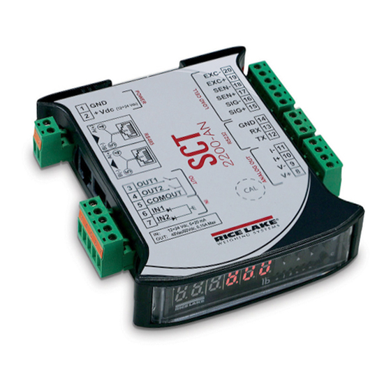
Overview The instrument has a plastic case; external dimensions and connections are shown in Figure 1-1. 119 mm 22.5 mm B(-) A( + ) B(-) A( + ) 2200AN RS232 LOADCELL ANALOG OUT Figure 1-1. SCT-2200 Dimensions and Connections Item No. Description GND power supply input (+) 12/24 VDC power supply input... - Page 8 Figure 1-2. SCT-2200 Front Panel Key or Item No. Description ZERO – Clears the displayed gross weight of up to ± 2% of the total capacity; Cancels a negative tare value In setup: scroll through parameters In numeric input: decreases the digit to be modified TARE –...
-
Page 9: Quick Setup Menu
Quick Setup Menu Press to turn the instrument on. Enter the quick setup menu by pressing as the firmware version displays. Press to set decimals and minimum division. DIV.DEC CEL.CAP Press , and to set the total capacity of the load cells. Press , and to set the mV/V sensitivity of the load cell. -
Page 10: Default Factory Calibration
1.3.1 Default Factory Calibration The instrument is shipped with the following default calibration settings: • Capacity – 10,000 kg • Load cell sensitivity – 2.000 mV/V • Division – 1 1.3.2 Theoretical Calibration Use the quick setup menu (Figure 1-3 on page 5 steps 1,2,3, and 4) to perform a theoretical calibration. -
Page 11: Installation
Installation Rice Lake Weighing Systems recommends the instrument and the platform (transducer) be installed on a flat level surface, that is stable and vibration free. Location Selection IMPORTANT The following should be considered when selecting a location for the equipment:... -
Page 12: Grounding The System
Grounding the System For proper grounding and optimal functioning of the system, it is necessary to create a single point ground in proximity of the instrument on which to connect the ground of the instrument connected cables. Connect the ground point of the instrument, load cells and weighing structure directly to the ground bar of the electric panel or to a grounding pole. -
Page 13: Connection To The Load Cell
Connection to the Load Cell After proper grounding of the platform and the load cell, connect the shielded cable from the load cell to the instrument ground. See Figure 1-1 on page The load cell terminal board of the instrument may be connected to the 6-wire load cell; 4-wire load cell must jumper sense to the excitation. -
Page 14: Wiring Schematic
Wiring Schematic SCT-2200 Analog Output IN 2 IN 1 RS-232 Load Cell RJ OUT RJ IN 12/24 Vdc • VE 12 / 24 Vdc POWER SUPPL Y 1. GND 0 Vdc (GND) 2. +Vdc +12 / 24 Vdc • LOAD CELL RECEPTORS CELL : 15. -
Page 15: Input/Output Wiring
Input/Output Wiring Figure 2-4. Input/Output Wiring The maximum power of the outputs 48 Vac 0,15 A max (or 60 Vdc 0,15 A max), the maximum voltage applicable to the inputs is between 12 and 24 Vdc with current from minimum 5 mA to maximum 20 mA. Installation... -
Page 16: Operation
Operation Basic Operation The instrument must be powered with stabilized voltage at 12 VDC or 24 VDC supplied from an AC/DC external charger (not included) which should be connected to appropriately rated AC main voltage. To power the instrument, connect the two power supply cables to the appropriate terminal board (Figure 1-1 on page 3) on the side or the back of the instrument. - Page 17 Cancel a Tare A tare value can be manually canceled in multiple ways: • Unload the scale and press • Press without unloading the scale • Enter a manual tare equal to zero Locked or Unlocked Tare When a tare value is entered manually, automatically or from storage, the tare value displays with a negative sign when the scale is unloaded.
-
Page 18: Auto Power Off
Tare Function Limitations It is possible to limit the tare functions by setting in the step . See Table 4-4 on page 35. The tare operations will have the following specifications: Scale Capacity Function (no remote display for the visualization of the tare) (remote display for the visualization of the tare) <220 lb All tare functions are disabled •... -
Page 19: Multi-Range Function
Multi-Range Function The multi-range function allows for subdividing the scale capacity in two, each up to 3000 divisions. Example: with a 10 kg cell platform it is possible to approve the weighing system with: Single range: 6 kg capacity and 2 g division (3000 div.) Dual range: 6/3 kg capacity and 2/1 g division (3000 + 3000 div.) Multi-range functioning is indicated by illumination of the relative LED identifying the operating range;... -
Page 20: Printing
Printing The following weight data can be programmed to print to a connected printer. See Section 6.10 on page • 4 heading lines of 24 characters • Gross weight • Tare weight • Net weight • Ticket number • Date and time (optional) •... -
Page 21: Re-Enabling Printouts And Instrument Functions
SCALES SCALES PRIMARY LINE 1 PRIMARY LINE 1 PRIMARY LINE 1 PRIMARY LINE 2 PRIMARY LINE 2 PRIMARY LINE 2 PRIMARY LINE 3 PRIMARY LINE 3 PRIMARY LINE 3 PRIMARY LINE 4 PRIMARY LINE 4 PRIMARY LINE 4 SCALES 1 10.00 lb SCALES 2 10.00 lb... -
Page 22: Selecting The Operating Mode
3. Press to scroll forward or back through the following data. • First range capacity • First range minimum weight • First range division • Second range division • Second range minimum weight • Second range division •... -
Page 23: Unit Of Measure Conversion
3.8.1 Unit of Measure Conversion This function toggles the displayed weight between the scale unit of measure and lb. • Press to toggle between the scale unit of measure. • Long press to enter the setpoint input menu. See Section 4.3 on page 41.... -
Page 24: Multi-Scale Repeater
3.8.4 Multi-Scale Repeater A system consists of one or more (up to 32) primary instruments connected to one or more weighing systems. All communicate with a secondary instrument, which acts as a weight repeater, on which it is possible to view or print the weight of each individual scale or the sum of the weight detected by the single scales. - Page 25 10. Press . Set the primary instrument mode. • – SCT • – DFWKR • – DFW • – CPWE • – 3590 11. Press to confirm settings. If there is more than one primary instrument, the secondary instrument displays .
-
Page 26: Alibi Memory
• Press twice on the secondary instrument to produce a menu: - – allows for quickly selecting a primary instrument (displays only if more than one primary) - – allows for input of a setpoint (only if there are functions linked to relays). If there are no functions linked to relays, the fast primary instrument selection displays and a prompt to enter the primary instrument number. - Page 27 The ID has the format: <Rewriting number>-<Weigh number> • The rewriting number is a five digit number from 00000 to 00255; it indicates the number of complete rewritings of the alibi memory • Weigh number is a six digit number from 000000 to 131072; it indicates the weigh number in the current rewriting of the alibi memory.
- Page 28 The alibi memory can be cleared directly on the instrument in the parameter. 1. Turn on the instrument and press while the firmware version displays. displays. 2. Press until displays. Press to enter the menu. 3. Press until displays. Press .
-
Page 29: Single Scale Repeater
Weight Reading Command: [II]ALRDXXXXX-YYYYYY <CR o CRLF> In which: • [II] is the RS-485 address • XXXXX is the rewriting number (from 00000 to 00255) • - is the hyphen character (ASCII decimal 45) • YYYYYY is the weighing number (from 000000 to 131072) Instrument response: [II]B,LLLLLLLLLLUU,YYTTTTTTTTTTUU<CR o CRLF>... -
Page 30: Sensitivity Times Ten
Example of settings for repeater/transmitter configuration: Unit Repeater 9600 n-8-1 All modes except Transmitter 9600 n-8-1 Table 3-3. Set Up Example 3.8.7 Sensitivity Times Ten This mode converts the weight to sensitivity time ten for display and is used for testing during calibration. Operation 1. -
Page 31: Horizontal Totalizer
4. Press to confirm. The instrument returns to the weigh mode. Time in Sample per Acquired Mediated 1/100 sec Second Values Values Table 3-4. Sample Times in Peak Weight Detection The peak detection function sensitivity is dependent on the parameter set. The higher the number of samplings, the greater the sensitivity. -
Page 32: Vertical Totalizer
Printing and Zeroing Totals The instrument has two different total levels, a partial total and a general total, which increase with each totalization. These can be printed and zeroed independently from each other. To print and zero a partial total, press . - Page 33 Press • cancels the previously set reference; momentarily displays (if there is not a valid reference, the message does not display) • After canceling a reference press to set a new reference value Operation Use a reference quantity equal to or greater than 0.1% of the scale capacity. The weight of the reference quantity should not create an APW lower than the two internal points of the converter (intrinsic limit of the scale).
-
Page 34: Simultaneous Transmitter Mode
Manual Entry of APW A known APW can be entered with the keyboard. To display the stored APW: . and the stored nine digit value with five decimal places displays in the • Press and hold programmed unit of measure. To enter a known APW: 1. -
Page 35: Setup Mode
Setup Mode The setup mode is used to set the functioning parameters of the instrument. To enter the setup mode, turn on the instrument and while the firmware version displays, press . The instrument displays the first parameter. Setup Mode Navigation Function Scroll through parameters In numeric input: decreases the digit to be modified... -
Page 36: Setup Mode Menu
Setup Mode Menu Figure 4-4 on page Figure 6-1 on page Figure 6-3 on page Figure 4-3 on page LEGEND = USER & TECH MENU = ONLY TECH MENU Figure 4-1. Setup Mode Menu SCT-2200 Weight Transmitter... -
Page 37: F.mode Parameters
4.2.1 F.Mode Parameters The function mode parameters set the functionality of the scale. Table 4-2. F.Mode Menu Parameter Settings Description Functioning Mode NOTE: For the details of the operating modes, see Section 3.8 on page Once the functioning mode is selected, if a printer is configured, the printout is automatically enabled. This parameter is not displayed if trAnSM is set in the tYPE parameter. - Page 38 Vertical totalizer – if this mode is selected, the type of totalization must also be set: normal (), fast () or automatic () Counting – if this mode is selected, the unit of measure of the average piece weight (APW) (g / kg / t / Lb) and the sampling interval in seconds () must also be set Screen Saver –...
-
Page 39: Setup Parameters
Figure 4-4 on page Figure 6-1 on page Figure 6-3 on page Figure 4-3 on page Figure 4-2. Setup Menu 4.2.2 Setup Parameters These parameters configure the scale. Parameter Settings Description Metrics configuration - See Table 4-7 on page 40 ... - Page 40 = C key – ON/OFF key = Turning off the instrument = Disables the keyboard Output configuration – Sets the function to be linked to each output out.1 - out.6 Configurations are valid for all outputs ...
-
Page 41: Analog Output
4.2.3 Analog Output xxxxxx xxxxxx xxxxxx Figure 4-3. Analog Output Menu Parameter Settings Description Section 6.9 on page 66 for configuring the analog output; This parameter is not displayed if is selected; – selects the slot to be used with the analog output: •... -
Page 42: Diagnostic Menu
4.2.4 Diagnostic Menu See the Figure 4-1 on page 32 for the diagnostic () menu structure. Settings Description Press to display the software version Press to display the calibration internal divisions; The parameter displays only in a primary instrument ... -
Page 43: Configuration Menu
Settings Description Analog Output Test – Provides a basic test to verify correlation of D/A and analog output, when equipped with analog output option; See Section 6.9 on page 66 Pres , then 00000 displays. Enter a value between 00000 and 65535 and confirm by pressing ;... - Page 44 Parameter Settings Description Selection of active channel; 1 to 4 in scales with non dependent channels functioning mode (/ NOTE: The parameter is not displayed if is set in the . parameter or ...
-
Page 45: Output Functions
Output Functions The instrument is fitted with two optoisolator photocoupler inputs and two Photo MOSFET outputs. See electric specifications in Section 2.5 on page 9 (Figure 4-5) the functioning mode of each of the outputs is set: In the setup menu •... - Page 46 Parameter Settings Description Define the functionality of each output No function, the output is inactive Setpoint on the gross weight Functioning with hysteresis ( parameter set at ) Enables output function on gross weight; Two setpoints for each output must be set; one which disables the output when the gross weight falls below it;...
- Page 47 Parameter Settings Description Setpoint on net weight. Setpoints are set in the same manner as gross weight; See1 GroS on page 42. In addition setpoints can be set and activated on a negative weight • Positive weight ( set at ) •...
-
Page 48: Calibration
Calibration The type of calibration used is dependent on the type of application chosen for the instrument. Procedure Use this procedure to calibrate the scale in either the or the mode. Each individual cell must be connected to an instrument channel. To connect more than four cells, it is necessary to trim the cells. while the firmware version displays. -
Page 49: Theoretical Calibration
22. If using multiple calibration points, the unit automatically advances to the next point (, ). Repeat steps through for each calibration point. Note The calibration points must be in increasing order (point 1 < point 2 < point 3). 23. - Page 50 18. Press until displays. Press to enter the menu. 19. Set the cell capacity in the configured unit of measure (0 to 999999) using to select the digit to be modified and to increase or decrease the digit. Press to confirm.
-
Page 51: Gravity Setting
Gravity Setting Use this procedure to correct the weight error caused by a different gravitational value between the calibration zone and the zone of use. 1. Turn on the instrument and press while the firmware version displays. displays. Press until ... -
Page 52: Communications
Communications Serial Menu Figure 6-5 on page XX.X Figure 6-1. Serial Menu SCT-2200 Weight Transmitter... - Page 53 Parameter Settings Description Select the PC communication port Communication between the instrument and the PC takes place through the RS-485 port and transmission of data to the printer through the RS-232 port Communication between the instrument and the PC takes place through the RS-232 port and transmission of data to the printer through the RS-485 port ...
- Page 54 Parameter Settings Description PC Serial Transmission on the PC Serial – In the secondary mode, this step is not displayed if the functioning mode has been set in the step; if the mode has been set, only the , , , ...
- Page 55 Parameter Settings Description (cont) – String length: Enter the number of digits (00 to 39) which make up the entire string transmitted from the serial line scale, less the terminator character. For example, if the transmitted (cont) string is spppppppuu + CR + LF, in which s is the weight sign, ppppppp is the weight value, uu is the unit of measure, set the value at 11.
-
Page 56: Serial Outputs
Parameter Settings Description RS-485 Serial Address – In the functioning mode it is possible to enable the RS-485 protocol and link its address to the instrument; the instrument then repeats the weight if the address in the received string is the same as set here ... -
Page 57: Com2 Serial Port
• The difference of potential between the A(+) and B(-) terminals in rest conditions must be of at least 0.2 V. To create a resistive divider which maintains this difference of potential also when all the transmitters are disabled, inert in the RS-485 port of the instrument where there are the termination resistances, the polarization or fail-safe resistance. - Page 58 Parameter Description Transmission in RS-485 serial mode – The protocol is the same as the transmission with request; the instru- ment responds only if its code is the one requested (before the request the machine code must be input, I.E. 00READ<CRLF>);...
-
Page 59: Serial Commands Format
6.3.3 PRN PORT This section describes the selectable serial weight transmission modes of the PRN serial port through the corresponding parameter in the setup mode. Parameter Description Transmission of data to the printer by pressing on the instrument; The print command is inhibited if ... - Page 60 Serial Errors The instrument transmits a response string or it transmits one of the following indications with each serial command received: Status Response Description OK<CR LF> Displays when a correct command is transmitted from the PC to the instrument; The OK does not imply that the instrument executes the zero ERR01<CR LF>...
- Page 61 Extended Weight Read Command With Date and Hour [CC]REXD<CR LF> Instrument response in the or in the mode: extended string (Section 6.5.2 on page 62). Instrument response in the mode: multi-scale string (Section 6.5.3 on page 63). Weight Read Command [CC]READ<CR LF>...
- Page 62 Converter Channel Switching Command [CC]CGCHN<CR LF> Instrument answer: [CC]OK<CR LF> if the CGCH command has been received. In which: N is the number of the channel on which to position the instrument Test Command [CC]ECHO<CR LF> Instrument response: [CC]ECHO<CR LF> Print Command [CC]PRNT<CR LF>...
- Page 63 Serial Command for Setting the APW (only for the counting operating mode) [CC]SPMUvvvvvvvv<CR LF> or [CC]Xvvvvvvvv<CR LF>. In which: vvvvvvvv is the APW (up to 8 characters with decimal point); maximum value: 9999.999 System response: [CC]OK<CR LF>. For example: to set a APW of 1.55 g, the command is the SPMU1.55<CR LF> or SPMU0001.550 <CR LF> and all the various combinations adding zeros to the right or to the left but taking into consideration that the maximum length of the APW field is 8 characters.
- Page 64 Scale Information Reading [CC]RALL<CR LF> Instrument response: [CC]SS,B,NNNNNNNUM,LLLLLLLUM,YYTTTTTTTTUM,XXXXXXXUM,SSS,AAA,CCC,TTT,XXXXX- YYYYYY<CR LF>. In which: Underload Overload Stability of the display Instability of the display Active inclination input Number of platform on which the totalization has been made NNNNNNNUM Net weight with unit of measure LLLLLLLUM Gross weight with unit of measure XXXXXXXUM...
-
Page 65: Transmission Protocols
Setpoint Saving Command [CC]CMDSAVE<CR LF> Response: [CC]OK<CR LF> Enable/Disable Keyboard To enable the keyboard: [CC]KEYEE<CR LF> Response: [CC]OK<CR LF> To disable the keyboard: [CC]KEYED<CR LF> Response: [CC]OK<CR LF> Transmission Protocols The weight data transmission on the PC and PRN serial ports may take place in 3 formats: standard string, extended string or multi-scale string. -
Page 66: Extended String
6.5.2 Extended String Without APW (any mode other than counting or in response to the REXT command): [CC]B,hh,NNNNNNNNNN,YYTTTTTTTTTT,PPPPPPPPPP,uu,(dd/mm/yybbhh:mm:ss|NO DATE TIME)<CR LF> With APW (in piece counting mode or in response to the REXT command): [CC]B,hh,NNNNNNNNNN,YYTTTTTTTTTT,PPPPPPPPPP,AAAA.AAAAA,uu<CR LF> In which: is the instrument code as two ASCII decimal digits (RS-485 protocol) [CC] scale number (1 in a scale with equalized channel mode (DEP.CH) the channel number from 1–4 in scale with independent channels mode (IND.CH). -
Page 67: Multi-Scale String
6.5.3 Multi-Scale String The string can vary depending on the configured channels: • [CC]hh,pppppppp,uu, (dd/mm/yybbhh:mm:ss|NO DATE TIME)<CR LF> • [CC]hh,pppppppp,uu,hh,pppppppp,uu, (dd/mm/yybbhh:mm:ss|NO DATE TIME)<CR LF> • [CC]hh,pppppppp,uu,hh,pppppppp,uu,hh,pppppppp,uu, (dd/mm/yybbhh:mm:ss|NO DATE TIME)<CR LF> • [CC]hh,pppppppp,uu,hh,pppppppp,uu,hh,pppppppp,uu,hh,pppppppp,uu, (dd/mm/yybbhh:mm:ss|NO DATE TIME)<CR LF> In which: is the instrument code as two ASCII decimal digits (RS-485 protocol) [CC] For each set channel: Stability of the display... -
Page 68: Remote Scale Configuration
Extended String Extended string transmitted on the print port when C, SS,NT,WWWWWWWW,UU<CR LF> In which: Secondary or sum:S, if the sum is sent; Secondary number, if 1 salve weight is sent Status (see standard string) WWWWWWWW weight unit of measure Carriage Return + Line Feed (ASCII decimal character 13 and 10). -
Page 69: Primary, Secondary And Repeater Mode Configurations
2. Compile the parameters table. Parameter LCD Text Value Remote scale terminator Remote scale weight position Remote scale weight length Remote scale tare position Remote scale tare length Remote scale tare type position Remote scale sting length Table 6-9. -
Page 70: Analog Output Option
SCT-1100 (secondary) 3590 /CPWE (primary) ; : : X : X (number of the primary instrument) : : : . Table 6-11. 3590 – RS-232 Connections SCT-1100 (secondary) 3590 /CPWE (primary) : ... - Page 71 Parameter Description Enter the capacity of the primary instrument; Set the corresponding value without a decimal point (for example, if the capacity of the scale is 30,000 kg, insert 030000); This parameter displays only if the mode is secondary ...
-
Page 72: Print Programming
Approximate Values Between The DA Converter and Analog Output DA Converter Voltage Current (mA) 1200 12700 58600 62650 Table 6-14. DA Converter and Analog Output Ao = Analog output Positive Weight Negative Weight Figure 6-4. Analog Output 6.10 Print Programming Once a printer has been configured correctly in the setup mode, the instrument carries out the print functions;... - Page 73 Figure 6-5. Print Programming Menu Parameter Description Select the language of the printouts: = Italian = English = German = French = Spanish Empty line at the beginning of the printout: = an empty line is inserted at the beginning of each printout = no empty line Table 6-15.
- Page 74 Parameter Description Printing of a heading in: Secondary mode = no heading = headers printed when the 1st primary instrument print is executed = headers printed when the primary instruments prints are executed = headers printed when the sum is printed = headers always printed Primary mode = no heading...
-
Page 75: Formatting Data And Layout
Parameter Description Print two empty lines at the end of each printout (if is selected in ) or an end label (if is selected in ) Secondary mode = does not print the page end = prints the end page when the primary instruments prints are executed = prints the end page when the sum is printed = end page is always printed Primary mode... - Page 76 Parameter Description The following parameters are displayed only if a setting other than is selected in the parameter. – Select the bar code vertical distance of preceding text: In lines with normal height font, programmable value is 0 to 9 (default 0) ...
- Page 77 Parameter Description Select the font type: = the data is printed using the font programmed in the step = the data is printed using the font programmed in the step Set the label width: Enter a three digit value, expressed in mm (default 063) ...
- Page 78 Parameter Description – Select the left margin Enter a two digit value, expressed in mm (default 15) – Select the bar code font height Enter a two digit value, expressed in mm (default 10) – Select the print fields in the bar code: ...
-
Page 79: Save The Label To Permanent Memory
Parameter Description By pressing , a label with the previously selected fields, but with fixed weight values, is printed The print test depends on the selected functioning mode: • mode: the first time the fields with the kg unit of measure are printed, the second time the fields with the lb unit of measure are printed, and so on •... -
Page 80: Troubleshooting
Troubleshooting Use the following table to troubleshoot error messages on the instrument. Message Description Displays when not connected at start-up, if there are communication problems between the instrument and the board or when the alibi memory operation is selected; The unit of measure conversion is automatically set, but not saved in the setup mode ... -
Page 81: Specifications
Specifications Power DC Communication Digital inputs/Outputs Power Supply 12/24 VDC 2 inputs opto isolated 12-24 VDC Power Consumption 5 mA min to 20 mA max 2 outputs 150 mA 48 VAC/150 mA 60 VDC 5 VDC, 120 mA, 8 x 350 Ω Excitation Voltage Analog Signal Input ±39 mV... - Page 82 SCT-2200 Weight Transmitter...
- Page 84 Specifications subject to change without notice. Rice Lake Weighing Systems is an ISO 9001 registered company. 230 W. Coleman St. • Rice Lake, WI 54868 • USA U.S. 800-472-6703 • Canada/Mexico 800-321-6703 • International 715-234-9171 • Europe +31 (0)26 472 1319 www.ricelake.com...
Need help?
Do you have a question about the SCT-2200 Advanced Series and is the answer not in the manual?
Questions and answers