Rice Lake SCT-2200 Advanced Series Technical Manual
Weight transmitter
Hide thumbs
Also See for SCT-2200 Advanced Series:
- Technical manual (84 pages) ,
- Quick setup manual (9 pages) ,
- Quick setup manual (2 pages)

Related Manuals for Rice Lake SCT-2200 Advanced Series


Summary of Contents for Rice Lake SCT-2200 Advanced Series
- Page 1 SCT-2200 Advanced Series Weight Transmitter Version 8. 04 Technical Manual July 24, 2019 PN 183522 Rev A...
- Page 2 All information contained within this publication is, to the best of our knowledge, complete and accurate at the time of publication. Rice Lake Weighing Systems reserves the right to make changes to the technology, features, specifications and design of the equipment without notice.
-
Page 3: Table Of Contents
Setup Parameters ................20 Technical training seminars are available through Rice Lake Weighing Systems. - Page 4 9.0 Specifications ............... . . 48 Rice Lake continually offers web-based video training on a growing selection of product-related topics at no cost.
-
Page 5: Introduction
This manual applies to indicators using version 8.00 or higher of the STC-2200 firmware. Configuration and calibration of the indicator can be accomplished by pressing the indicator front panel keys, the serial command set or Rice Lake Tools configuration utility. Each indicator is designed to work with one scale and has the capability to be daisy chained to one protocol interface to communicate with a network interface controller for larger jobs. -
Page 6: Options
SCT-2200 Weight Transmitter General Safety Continued Failure to follow could result in damage to equipment or corruption to and loss of data. IMPORTANT Keep away from heat sources and direct sunlight. Protect the instrument from environmental factors: rain, snow, dust, etc. Do not wash, dip in water or spill liquid on the instrument. -
Page 7: Overview
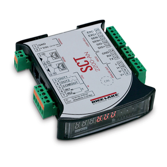
Connection for serial line RS-485 Digital I/O Analog output (PN 182589 only) Connection for serial line RS-232 Connection for load cell Access point to J1 to restrict calibration Table 1-1. SCT-2200 Connections © Rice Lake Weighing Systems ● All Rights Reserved... -
Page 8: Panel Display
SCT-2200 Weight Transmitter 1.3.1 Panel Display The front panel of the SCT-2200 consists of a display with six digits that are 0.31 in (8 mm) high, six LED annunciators and a five key keyboard. Figure 1-2. SCT-2200 Front Panel Item No. Symbol Description ZERO –... -
Page 9: Installation
Installation Installation Rice Lake Weighing Systems recommends the instrument and the platform (transducer) be installed on a flat level surface, that is stable and vibration free. Location Selection The following should be considered when selecting a location for the equipment: IMPORTANT •... -
Page 10: Grounding The System
SCT-2200 Weight Transmitter Grounding the System A centrally located, single point ground, such as the ground bar of the electric panel, must be created and/or identified for proper grounding and functioning of the system. The ground must be sized so that the total resistance of grounding is lower than 1Ω. -
Page 11: Wiring Schematic
J1 disables/enables calibration menu in SCT-2200 firmware. This function allows calibration to be limited to authorized personnel. Access to J1 is possible by breaking seal in SCT-2200 label. Restrict access to calibration by Note jumpering J1 and covering CAL access hole with tamper proof sticker. © Rice Lake Weighing Systems ● All Rights Reserved... -
Page 12: Connection To The Load Cell
SCT-2200 Weight Transmitter Connection to the Load Cell The load cell terminal board of the SCT-2200 must be connected to the 6-wire load cell; if using a 4-wire load, cell excitation must jumper to sense. Sense is always enabled and, when not using 6-wire load cell, the sense terminals must be jumpered to the IMPORTANT same polarity excitation wires. -
Page 13: Operation
To completely power off the unit, remove the power supplied voltage. 3.1.4 Zero Press to zero a gross weight within ± 2% of the total capacity (or as set). Weight value displays as 0 and the relative annunciators illuminate. © Rice Lake Weighing Systems ● All Rights Reserved... -
Page 14: Tare
SCT-2200 Weight Transmitter 3.1.5 Tare Semiautomatic Tare Press to tare the weight value on the scale. tArE displays momentarily and then 0 (net weight). The relative annunciators illuminate. Manual Tare Press for a few seconds. -tM- displays and then 000000. Enter the desired tare value with the following keys: •... -
Page 15: Multi-Range Function
5. Press to confirm. 6. Slowly press multiple times until SAVE?displays. • Press to confirm and store to the instrument memory • Press any other key to cancel and exit without saving © Rice Lake Weighing Systems ● All Rights Reserved... -
Page 16: Selecting The Operating Mode
SCT-2200 Weight Transmitter Selecting the Operating Mode In addition to the standard weighing mode, the instrument can be set to carry out four alternative operational functions. Each operating mode activates certain LEDs. To set the operating mode: 1. Turn on the instrument and press while the firmware version displays. -
Page 17: Sensitivity Times Ten
10. © Rice Lake Weighing Systems ● All Rights Reserved... -
Page 18: Peak Hold Weight Detection
SCT-2200 Weight Transmitter 3.5.4 Peak Hold Weight Detection This mode can be used to store the maximum (peak) weight value measured during the weighment. Operation If Peak Hold Weight Detection has been set as the functioning mode, the following functions are enabled while in weigh mode: 1. -
Page 19: Setup Mode
In setup: press multiple times to display SAvE? prompt and/or press to exit a step without confirming the setting In numeric input: clears the present value Table 4-1. Key Functions in Setup Mode © Rice Lake Weighing Systems ● All Rights Reserved... -
Page 20: Quick Setup Menu
SCT-2200 Weight Transmitter Quick Setup Menu Press to turn the instrument on. Enter the quick setup menu by pressing as the firmware version displays. After every parameter, press enter to accept settings. Press to set decimals and minimum division. DIV.DEC Press to set the scale capacity. -
Page 21: Default Factory Calibration
Section 4.3.2 on page 20 for Input setup parameters. 4.2.6 Output Functions Section 4.5 on page 25 for Output Functions. 4.2.7 Fieldbus Parameters For detailed Fieldbus configuration information, See Fieldbus Card Manual (RLWS Part #183523). © Rice Lake Weighing Systems ● All Rights Reserved... -
Page 22: Setup Mode Menu
SCT-2200 Weight Transmitter Setup Mode Menu F.Mo de FuNCT Con ver aLi bi REACT zero aLWAYS viss i nst peaK LoCK TARE disab u nLOCK RS.ZERo disab ENAB Figure 4-5 on Con fiG setu p page 22 dsp. rf NoRM 1 hz 2.5 hz di aG... -
Page 23: F.mode Parameters
UnloCk Enables restoring the last captured zero after a power cycle rs.zero Disables restore zero after power cycle disab Enables restore zero after power cycle Enab Table 4-2. Function Mode Parameter © Rice Lake Weighing Systems ● All Rights Reserved... -
Page 24: Setup Parameters
SCT-2200 Weight Transmitter 4.3.2 Setup Parameters setu p Figure 4-5 on page Con fiG dsp. rf NoRM 1 hz 2.5 hz 5 hz 10 hz Figure 6-1 on 20 hz page seri al ni. al i. aLi b.? Figure 4-6 on page i n pu ts Figure 4-6 on... -
Page 25: Diagnostic Menu
Serial Number – Displays the instrument’s serial number SEr.nuM Press to select the desired radio channel; OKdisplays if the configuration is successful, ERRoR displays if not successful S.radio Table 4-4. Diagnostics Menu © Rice Lake Weighing Systems ● All Rights Reserved... -
Page 26: Configuration Menu
SCT-2200 Weight Transmitter Configuration Menu Setu p CONF IG Figure 4-2 on page 18 for full menu FLT 3 - 0 navigation. fiLT.50 CUSTOM F.F.400 F.F.200.3 - .1 F.F.50.3 - .1 DYN.3 - .0 hR .6 - .0 F.F.100.4 - .1 param stabiL DI.SAB... - Page 27 Section 5.4 on page 33 GraV, Scale calibration – See Section 5.0 on page 30 Calib Zero calibration – See Section 5.0 on page 30 0.CaLib Table 4-5. Config Menu Parameters and Settings © Rice Lake Weighing Systems ● All Rights Reserved...
-
Page 28: Filter Parameters
SCT-2200 Weight Transmitter 4.4.1 Filter Parameters Standard digital filtering uses mathematical averaging to compensate for the noise that the A/D converter sends periodically because of external vibration. This filter compensation makes data less susceptible to a DC signal bias error for some signals. Each of the filters of the SCT-2200 are intended to compensate for different types and intensities of digital noise and vibration. -
Page 29: Input/Output Functions
– Turning off the instrument – C key – ON/OFF key – Print key print – Mode key (Default for input 2) Mode – Tare key tare Table 4-7. Input Functions © Rice Lake Weighing Systems ● All Rights Reserved... -
Page 30: Output Functions
SCT-2200 Weight Transmitter 4.5.2 Output Functions The parameters of each of the outputs is set in the setup outPut menu, See Figure 4-6. Some of functioning modes of the outputs are relative to the specific functioning modes of the instrument; see the Note following descriptions for the details. - Page 31 In a switching condition with stability, the output is enabled only when the weight is stable. The delay time is evaluated when a setpoint on gross weight or setpoint on net weight is selected as an output function. Table 4-8. Output Functions (Continued) © Rice Lake Weighing Systems ● All Rights Reserved...
-
Page 32: Analog Output Option
SCT-2200 Weight Transmitter Analog Output Option An optional analog output is configurable at 0-20mA, 4-20mA, 0-10Vdc, 0-5Vdc; with minimum and maximum settable values. The output voltage and the current from the interface are proportional to the gross weight or net weight present on the scale. The analog output is updated every 20ms and takes on the value corresponding to the weight converted in that instant;... - Page 33 Approximate Values Between The DA Converter and Analog Output: D/A Converter Voltage Current (mA) 1200 12700 58600 62650 Table 4-10. DA Converter and Analog Output Ao = Analog output Positive Weight Negative Weight Figure 4-8. Analog Output © Rice Lake Weighing Systems ● All Rights Reserved...
-
Page 34: Calibration
SCT-2200 Weight Transmitter Calibration Calibration Menu The indicator can be calibrated using a known weight or theoretically. Figure 4-5 on page 100000 Grav. xxxxx 1.000 1.00 setup CONFIG Calib deCi u.m. 0.CALib ranGe ranGe 2 N TP CALib.p TP 0 XXXXXX DDT1 TP 1... -
Page 35: Calibration Parameters
5. Set the total capacity of the scale, or ranGe1 if using multi-range functioning. Press to confirm. See Section 3.2 on page 11 for more information on multi-range functioning. © Rice Lake Weighing Systems ● All Rights Reserved... -
Page 36: Theoretical Calibration
SCT-2200 Weight Transmitter 6. For dual range scale only: • Navigate to select rAnGE 2 . Press to set parameter. • Set the second range. Press to confirm. Calib.P displays. Press to enter the menu. ntP displays. Press to set parameter. is disabled if set at 000000. -
Page 37: Setting Local Gravity
The gravity correction function has not been evaluated by an approvals agency, therefore it is up to the authorized scale dealer to ensure the device is accurate at the intended point of use. IMPORTANT © Rice Lake Weighing Systems ● All Rights Reserved... -
Page 38: Zero Dead Load A/D Counts
SCT-2200 Weight Transmitter Zero Dead Load A/D Counts Table 5-2 lists the ideal A/D counts that result from input signals of 0Ð45 mV with zero deadload. Actual values will typically be higher than the values shown in Table 5-2 but the ideal values can be used when calibrating the indicator with no attached scale. -
Page 39: Communications
The COM2 serial port is bi-directional (full duplex) and uses an RS-232 for transmitting data. It is mainly used to connect printers, PCs, and PLCs. The transmission speed may be selected in the setup as: 1200, 2400, 4800, 9600, 19200, 38400, 57600, 115200 baud. © Rice Lake Weighing Systems ● All Rights Reserved... -
Page 40: Serial Port Transmission Modes
SCT-2200 Weight Transmitter Serial Port Transmission Modes Setu p Seri aL pC SEL pr-no PrPC. hk repe.6 prpC. ex 9600 prpC.st 4800 aLL. ext 2400 ALL.std Co m. prn Pr Mo de 1200 n-8-1 115200 o-8-1 57600 bau d. pr o-7-2 38400 o-7-1... -
Page 41: Prn Port
Manufacturer Use Only Pwr.Prn Manufacturer Use Only Prn.Cts Select Language of Printouts Pr.Conf Lang NOTE: Language selection only available if tpr is selected Table 6-3. PRN Port Parameters and Settings © Rice Lake Weighing Systems ● All Rights Reserved... -
Page 42: Pc Port
SCT-2200 Weight Transmitter 6.2.3 PC PORT This section described the selectable serial weigh transmission modes of the PC serial port. Parameter Settings Description Serial format for the PC port CoM. PC Transmission on the PC port PC Mode Transmission with the MODBUS protocol Modbus •... -
Page 43: Serial Commands Format
• vvv is the firmware version • b is the space character, ASCII 32 Instrument responds if the command has been received. No response is sent when the instrument has executed the command. Note © Rice Lake Weighing Systems ● All Rights Reserved... - Page 44 SCT-2200 Weight Transmitter Extended Weight Read Command [CC]REXT<CR LF> Instrument response: extended string, See Section 6.4.2 on page 44 Weight Read Command [CC]READ<CR LF> Instrument response: standard string, See Section 6.4.1 on page 44 Weight Reading Command With Sensitivity Times 10 [CC]GR10<CR LF>...
- Page 45 Instrument in print test Instrument in firmware update phase Instrument in standby Instrument in automatic zero phase Instrument in change channel Instrument in inputs test phase Table 6-7. Instrument Status Commands © Rice Lake Weighing Systems ● All Rights Reserved...
- Page 46 SCT-2200 Weight Transmitter Key Press Simulation Command [CC]KEYPXX<CR LF> In which: Code of Pressed Key - ZERO key - TARE key - MODE key - PRINT key - C key Numeric 1 key Numeric 2 key Numeric 3 key Numeric 4 key Numeric 5 key Numeric 6 key Numeric 7 key...
- Page 47 Setpoint Saving Command [CC]CMDSAVE<CR LF> Response: [CC]OK<CR LF> Enable/Disable Keyboard To enable the keyboard: [CC]KEYEE<CR LF> Instrument response: [CC]OK<CR LF> To disable the keyboard: [CC]KEYED<CR LF> Instrument response: [CC]OK<CR LF> © Rice Lake Weighing Systems ● All Rights Reserved...
-
Page 48: Transmission Protocols
SCT-2200 Weight Transmitter Transmission Protocols The weight data transmission on the PC and PRN serial ports will take place in one of two formats: standard string or extended string. 6.4.1 Standard String String transmitted: [CC]hh,kk,pppppppp,uu <CR LF> In which: Characters Description [CC] The instrument ID as two ASCII decimal digits (RS-485 protocol) -
Page 49: Secondary Mode Strings
Table 6-13. Extended String Characters When is selected the weight value is always zero. REPE.6 Note When the is set, only the weight is transmitted on the printer port. PR.MODE PcPR.hk © Rice Lake Weighing Systems ● All Rights Reserved... -
Page 50: Troubleshooting
SCT-2200 Weight Transmitter Troubleshooting Use the following table to troubleshoot error messages on the instrument. Message Description Displays when not connected at start-up, if there are communication problems between the instrument and the board or when the alibi AL.Err memory operation is selected; The unit of measure conversion is automatically set, but not saved in the setup mode Printing - PRN serial port is occupied or the instrument is waiting to transmit a print job to a PC bUSy Trying to print with an unstable weight... -
Page 51: Compliance
CONFORMITY SCT indicator series 2014/30/EU EMC EN 61000-6-2:2015, EN 61000-6-4:2007+A1:2011, EN61326-1:2013, EN55011:2009 +A1:2010 2014/35/EU LVD EN 61010-1:2010 2011/65/EU RoHS EN 50581:2012 __________________________ ________________ _________ __________________________ __________________________ May 3, 2019 __________________________ __________________________ © Rice Lake Weighing Systems ● All Rights Reserved... -
Page 52: Specifications
SCT-2200 Weight Transmitter Specifications Power DC Communication Power Supply 12-24 VDC Digital inputs/Outputs Power Consumption 70 mA min to 100 mA max 2 inputs opto isolated 12-24 VDC Excitation Voltage 5 VDC, 120mA, 8 x 350Ω 2 outputs 150 mA 48 VAC/150 mA 60 VDC Analog Signal Input ±39 mV Range... - Page 54 Specifications subject to change without notice. Rice Lake Weighing Systems is an ISO 9001 registered company. 230 W. Coleman St. • Rice Lake, WI 54868 • USA U.S. 800-472-6703 • Canada/Mexico 800-321-6703 • International 715-234-9171 • Europe +31 (0)26 472 1319...
Need help?
Do you have a question about the SCT-2200 Advanced Series and is the answer not in the manual?
Questions and answers