Table of Contents
Advertisement
Advertisement
Table of Contents

Related Manuals for Rice Lake 420 Plus


Summary of Contents for Rice Lake 420 Plus
- Page 1 420 Plus HMI Digital Weight Indicator Version 1.14 Installation Manual 85127...
-
Page 3: Table Of Contents
Course descriptions and dates can be viewed at www.ricelake.com/training or obtained by calling 715-234-9171 and asking for the training department. © 2012 Rice Lake Weighing Systems. All rights reserved. Printed in the United States of America. Specifications subject to change without notice. - Page 4 7.12 Specifications..............53 420 Plus Limited Warranty ........................54 Rice Lake continually offers web-based video training on a growing selection of product-related topics at no cost. Visit www.ricelake.com/webinars.
-
Page 5: About This Manual
Normal mode is the “default” mode of the indicator. The indicator displays gross or net weights as required, using the LED annunciators described in Section 1.3 on page 2 to indicate 420 Plus Installation Manual - Introduction... -
Page 6: Front Panel Keypad
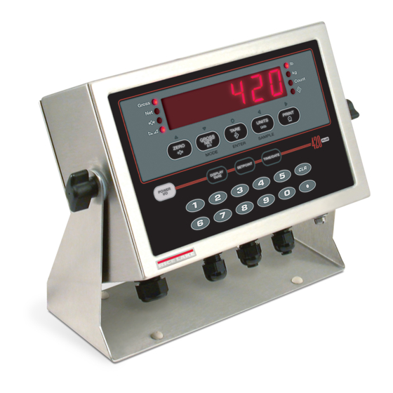
SAMPLE POWER DISPLAY SETPOINT TIME/DATE TARE Figure 1-1. 420 Plus Front Panel, Showing LED Annunciators and Normal Mode Key Functions LED Annunciators displayed). The LEDs function as primary and secondary units annunciators for 420 Plus display uses a set of eight LED... -
Page 7: Indicator Operations
Acquire Tare 1. Press to show the stored tare DISPLAY TARE 1. Place container on scale and wait for the value. standstill annunciator ( 2. Press the key twice to remove the CLEAR stored tare. 420 Plus Installation Manual - Introduction... -
Page 8: Acquire Parts Sample
3. Once activated, the digital input will go into To display the date, press the key once; ID mode. TIME/DATE press a second time to display the time. TIME/DATE 4. Enter the ID using the numeric keypad and press TARE 420 Plus Installation Manual... -
Page 9: Installation
If any parts were damaged in shipment, the indicator: one for the power cord, three to accommodate load cell, communications, digital notify Rice Lake Weighing Systems and the shipper inputs, and analog output cables. Two of the three free immediately. -
Page 10: Cable Grounding
• Route stripped cables through cord grips and clamps. Ensure shields contact grounding clamps as shown in Figure 2-2. Tighten grounding clamp nuts. Figure 2-3. 420 Plus CPU and Power Supply Board JMP1 Shunt Location 420 Plus Installation Manual... - Page 11 Figure 2-4. 420 Plus CPU and Power Supply Board 420 Plus Installation Manual - Installation...
-
Page 12: Dc Power Wiring Guidelines
Figure 2-5. 420 Plus DC Power Supply 2.3.3 DC Power Wiring Guidelines Cable Wire Gauge Impedance Based on: (AWG) (OHMS/1000ft) • 8 x 350 2.252 • Analog output installed 3.184 • Digital outputs sourcing 20mA each 4.016 •... -
Page 13: Load Cells
Table 2-4. J2 and J6 Pin Assignments communications only; the serial port provides either active 20 mA output or duplex RS-232 transmission. Both ports are configured using the SERIAL menu. See Section 3.0 on page 14 for configuration information. 420 Plus Installation Manual - Installation... -
Page 14: Analog Output
Use the torque pattern shown in Figure 2-6 to prevent distorting the backplate gasket. Torque screws to 15 in-lb (1.7 N-m). Torque Pattern Figure 2-6. 420 Plus Enclosure Backplate 420 Plus Installation Manual... -
Page 15: Replacement Parts
Ground wire 4 in, No. 8 (1) 14626 Kep nuts, 8-32NC Hex (5) 15627 Locknuts (3) 85494 Protective cover (1) Figure 2-9 13 15376 Standoffs, male - female (6) Fuse, 2.5 Amp 5x20mm 85791 Table 2-6. Replacement Parts 420 Plus Installation Manual - Installation... - Page 16 From Power Cord (16) To J7 header on PC Board (6) 5-pin overlay 8-pin overlay To backplate (3) From power cord (16) Ground Wire Detail Figure 2-8. 420 Plus Overlay and Power Supply 420 Plus Installation Manual...
- Page 17 Figure 2-9. 420 Plus Enclosure, Backplate and CPU Board 420 Plus Installation Manual - Installation...
-
Page 18: Configuration
See Section 5.0 on page 33 for more information about using the EDP command set. Figure 3-1. Sample Revolution Configuration Display 420 Plus Installation Manual... -
Page 19: Front Panel Configuration
Assign digital input functions. ALGOUT Analog Output Configure analog output module. Used only if analog output option is installed. VERS Version Display installed software version number. Table 3-1. 420 Plus Menu Summary Move RIGHT/ Move UP/ ENTER value Next Increrement Move DOWN/... -
Page 20: Menu Structures And Parameter Descriptions
The factory default setting appears at the top of each column in bold type. Most menu diagrams are accompanied by a table that describes all parameters and parameter values associated with that menu. Default parameter values are shown in bold type. 420 Plus Installation Manual... -
Page 21: Configuration Menu
1.9% around the calibrated zero point, for a total range of 3.8%. Indicator must be at standstill to zero the scale. Use the default value for legal-for-trade applications. Table 3-2. Configuration Menu Parameters 420 Plus Installation Manual - Configuration... - Page 22 Tare function. Enables or disables push-button and keyed tares. Possible values are: NOTARE BOTH:Both push-button and keyed tares are enabled PBTARE NOTARE:No tare allowed (gross mode only) KEYED PBTARE:Push-button tares enabled KEYED:Keyed tare enabled Table 3-2. Configuration Menu Parameters (Continued) 420 Plus Installation Manual...
-
Page 23: Format Menu
DSPRAT 250MS Display rate. Sets the update rate for displayed values. Values are in milliseconds (MS) or 500MS seconds (SEC). 750MS 1SEC 1.5SEC 2SEC 2.5SEC 3SEC 4SEC 6SEC 8SEC Table 3-3. Format Menu Parameters 420 Plus Installation Manual - Configuration... - Page 24 See Section 7.6 on page 48 for a list of multipliers. keyboard Multipliers are pre-configured within the indicator. Manual entry is only necessary when NONE is selected under UNITS. To toggle between primary and secondary units, press the UNITS key. Table 3-3. Format Menu Parameters (Continued) 420 Plus Installation Manual...
-
Page 25: Calibration Menu
Always use this parameter after WZERO and WSPAN have been set to re-capture a new zero value. See Section 4.1 on page 30 for more information about using this parameter. Table 3-4. Calibration Menu Parameters 420 Plus Installation Manual - Configuration... -
Page 26: Serial Menu
PRINT is momentarily displayed on the remote display. Level 3 Submenus EDP Port and Printer Port BAUD 9600 Baud rate. Selects the transmission speed for the EDP or printer port. 1200 2400 4800 19200 38400 Table 3-5. Serial Menu Parameters 420 Plus Installation Manual... -
Page 27: Program Menu
COUNT ACCESS Specifies whether operator has access to piece count mode and the default sample size used SPLSIZ for parts counting. See level three submenu for parameter descriptions. Table 3-6. Program Menu Parameters 420 Plus Installation Manual - Configuration... - Page 28 Specifies the format used to display or print the date. DDMMYY YYMMDD DATSEP SLASH Specifies the date separator character. DASH SEMI TIMFMT 24HOUR Specifies the format used to display or print the time. 12HOUR Table 3-6. Program Menu Parameters (Continued) 420 Plus Installation Manual...
-
Page 29: Print Format Menu
XXXXXXX ALGOUT VERS XXXXXXX SETPT1 SETPT2 Same as SETPT1 ENABLE KIND V ALUE TRIP BNDVAL HYSTER ACCESS GROSS HIGHER number number number LOWER If TRIP = HIGHER/ INBAND LOWER OUTBAND Figure 3-11. Setpoint Menu 420 Plus Installation Manual - Configuration... - Page 30 Front panel access to setpoints. Specify OFF if setpoints will not be used. ON enables operator to turn setpoints on/off, change value, or change BANDVAL via front panel entry during weigh mode. Table 3-7. Setpoint Menu Parameters 420 Plus Installation Manual...
-
Page 31: Digital Input Menu
• HOLD holds the current display. Releasing this input clears the running average filter. KBDLOC • CLRTAR clears the tare. HOLD • ACCUM displays the accumulator. CLRTAR • CLRACC clears the accumulator. ACCUM • NEWID enters the ID number. CLRACC NEWID Table 3-8. Digital Input Menu Parameters 420 Plus Installation Manual - Configuration... -
Page 32: Analog Output Menu
Tweak span. Adjust the analog output span calibration. Use a multimeter to monitor the analog output value. Press and hold to adjust the output. Press to save the new value. Table 3-9. Analog Output Menu Parameters 420 Plus Installation Manual... -
Page 33: Version Menu
The VERS menu is used to check the software version and reg version installed in the indicator. You can also check the indicator model. VERS CONFIG FORMAT XXXXXXX CALIBR SERIAL PROGRM PFORMT XXXXXXX SETPNT XXXXXXX DIGI N ALGOUT Software version Figure 3-14. Version Menu 420 Plus Installation Manual - Configuration... -
Page 34: Calibration
Press again to save WSPAN the calibration value and go to the next prompt ( PT-> 2 5. With displayed, place test weights on WSPAN the scale and press to calibrate span. The 420 Plus Installation Manual... -
Page 35: Edp Command Calibration
5. Up to five linearization points can be c a l i b r a t e d b e t w e e n t h e z e r o a n d s p a n 420 Plus Installation Manual - Calibration... -
Page 36: More About Calibration
2.0 mV/V 838,908 1,100,668 2.5 mV/V 3.0 mV/V 1,174,446 Table 4-1. Ideal A/D Raw Counts When Raw A/D Count is displayed, the six most significant digits appear. Scroll left or right to see the full value. 420 Plus Installation Manual... -
Page 37: Edp Commands
Press number 7 shifts to net mode when the tare is entered. Press number 8 Press number 9 KDOT Press the decimal point (.) KENTER Press the ENTER key Table 5-1. EDP Key Press Commands 420 Plus Installation Manual - EDP Commands... -
Page 38: Reporting Commands
Digital filter cutout sensitivity 2OUT, 4OUT, 8OUT, 16OUT, 32OUT, 64OUT, 128OUT DFTHRH Digital filter cutout threshold NONE, 2DD, 5DD, 10DD, 20DD, 50DD, 100DD, 200DD, 250DD TAREFN Tare function BOTH, NOTARE, PBTARE, KEYED Table 5-3. CONFIG EDP Commands 420 Plus Installation Manual... - Page 39 Stream rate INDUST, LFT PRNDEST Print destination EDP, PRN PRNMSG Print message OFF, ON Table 5-6. SERIAL EDP Commands Command Description Values PWRUPMD Power up mode GO, DELAY Table 5-7. PROGRM EDP Commands 420 Plus Installation Manual - EDP Commands...
- Page 40 Setpoint access OFF, ON Table 5-9. SETPNTS EDP Commands Command Description Values DIGIN1 Digital input function OFF, ZERO, TARE, NT/GRS, UNITS, DSPTAR, PRINT, CLRCN, DIGIN2 KBDLOC, HOLD, CLRTAR, ACCUM, CLRACC, NEWID Table 5-10. DIG IN EDP Commands 420 Plus Installation Manual...
-
Page 41: Normal Mode Commands
UU Transmit current part count nnnnnn PC Query system error conditions nnnnn nnnnn See Section 7.1.2 on page 43 for detailed information about the XE command response format. Table 5-12. Normal Mode Commands 420 Plus Installation Manual - EDP Commands... -
Page 42: Saving And Transferring Data
P C a s once the indicator receives settings for baud rate (BAUD ASCII-formatted text. parameter) or data bits and parity (BITS parameter) that do not match those configured for the PC. 420 Plus Installation Manual... -
Page 43: Print Formatting
<W> Current piece weight PT (preset tare) is added to the tare weight if tare was <SPnn> Space (nn = number of spaces)* keyed in. Table 6-1. Print Format Commands 420 Plus Installation Manual - Print Formatting... -
Page 44: Customizing Print Formats
Scroll right in format string characters of format Display and edit active character and Decrement ASCII value of active character Increment ASCII value of active character ASCII value Delete active character Figure 6-1. PFORMT Menu, Showing Alphanumeric Character Entry Procedure 420 Plus Installation Manual... -
Page 45: Using Revolution
Figure 6-2 shows an example of the Revolution print formatting grid. Figure 6-2. Revolution Print Format Grid 420 Plus Installation Manual - Print Formatting... -
Page 46: Appendix
Only shows up in Config mode. WVAL > 100,000 CNTERR Count error, insufficient sample size Reconfigure, parts sample too small for current configuration EEPERR EEPROM error Call Rice Lake Weighing Systems (RLWS) for service Table 7-1. 420 Plus Error Messages 420 Plus Installation Manual... -
Page 47: Using The Xe Edp Command
ADC Range 0100 0000 0000 0000 Table 7-3. Status Codes Returned on the ZZ Command 0x8000 Gross Limit 1000 0000 0000 0000 Reserved 0x10000 - 0x80000000 Table 7-2. Error Codes Returned on XE Command 420 Plus Installation Manual - Appendix... -
Page 48: Continuous Output (Stream) Format
Weight data: 7 digits, right-justified, with decimal point, l eading zer o s upr e ssion. Overload = ^^^^^^^ Underrange = ] ] ] ] ] ] ] Display overflow = OVERFL Figure 7-1. Continuous Output Data Format 420 Plus Installation Manual... -
Page 49: Ascii Character Chart
’ Ctrl-H Ctrl-I Ctrl-J Ctrl-K Ctrl-L Ctrl-M Ctrl-N Ctrl-O Ctrl-P Ctrl-Q Ctrl-R Ctrl-S Ctrl-T Ctrl-U Ctrl-V Ctrl-W Ctrl-X Ctrl-Y Ctrl-Z Ctrl-[ Ctrl-\ < Ctrl-] Ctrl-^ > Ctrl-_ Table 7-4. ASCII Character Chart (Part 1) 420 Plus Installation Manual - Appendix... - Page 50 Å » É æ ± Æ ô ö ò û ÷ ù ˘ ÿ ° Ö • Ü ¢ £ ¥ ² ƒ Table 7-5. ASCII Character Chart (Part 2) 420 Plus Installation Manual...
-
Page 51: Front Panel Display Characters
Front Panel Display Characters Figure 7-2 shows the 7-segment LED character set used to display alphanumeric characters on the 420 Plus front panel. < & > Figure 7-2. 420 Plus Display Characters 420 Plus Installation Manual - Appendix... -
Page 52: Conversion Factors For Secondary Units
0.001000 metric tons metric tons 2204.62 pounds 1000.00 kilograms 1.10231 short tons 0.984207 long tons long tons 2240.00 pounds 1016.05 kilograms 1.12000 short tons 1.01605 metric tons Multipliers in italics are preconfigured Table 7-6. Conversion Factors 420 Plus Installation Manual... -
Page 53: Digital Filtering
3rd Stage Displayed Filter A verage Filter A verage Filter A verage Value Figure 7-4. Flow Diagram for 420 Plus Digital Filters 7.7.1 DIGFLx Parameters 7.7.2 DFSENS and DFTHRH Parameters The first three digital filtering parameters, DIGFL1, The three digital filters can be used by themselves to... -
Page 54: Setting The Digital Filter Parameters
• For current output, connect ammeter 6. Return to normal mode. Analog output leads to pins one and two function can be verified using test weights. 420 Plus Installation Manual... -
Page 55: Test Mode
Press setup switch and Enter key at the same time to reset configuration and calibration parameters to factory default values. Load cells must be recalibrated before using the indicator (see Section 4.0 on page 30). Table 7-7. Test Mode Menu Functions 420 Plus Installation Manual - Appendix... -
Page 56: 7.10 Regulatory Mode Functions
On when lit (active low) Power Supply DI 2 (Digital In 2) On when lit (active low) LED (+5AV) Excitation/ADC supply on LED (+5V & +3.3V) Digital logic supply on 420 Plus Installation Manual... -
Page 57: 7.12 Specifications
Signal, excitation, and sense lines protected by capacitor bypass Analog Output Optional: fully isolated, voltage or current output,14-bit resolution. Voltage output: 0 –10 VDC Load resistance:1K minimum Current output: 4–20 mA External loop resistance: 500 maximum 420 Plus Installation Manual - Appendix... -
Page 58: 420 Plus Limited Warranty
420 Plus Limited Warranty Rice Lake Weighing Systems (RLWS) warrants that all RLWS equipment and systems properly installed by a Distributor or Original Equipment Manufacturer (OEM) will operate per written specifications as confirmed by the Distributor/OEM and accepted by RLWS. All systems and components are warranted against defects in materials and workmanship for two years. - Page 60 PN 85127 05/12...
Need help?
Do you have a question about the 420 Plus and is the answer not in the manual?
Questions and answers