Table of Contents
Advertisement
Quick Links
Advertisement
Table of Contents

Subscribe to Our Youtube Channel
Related Manuals for Maxxus 4.2 R


Summary of Contents for Maxxus 4.2 R
- Page 1 MAXXUS 4.2 R Bike...
- Page 2 This publication may not be reproduced, stored in a retrieval system, or transmitted in whole or in part, in any form or by any means, electronic, mechanical, photocopying, recording, or otherwise without the prior written permission of Maxxus Group GmbH & Co. KG.
-
Page 3: Safety Instructions
− It is recommended permanently to place a MAXXUS® Floor Protection Mat under the device to protect damageable floors such as wood, laminates, floor tiles etc. Please ensure that the mat cannot slip or slide. -
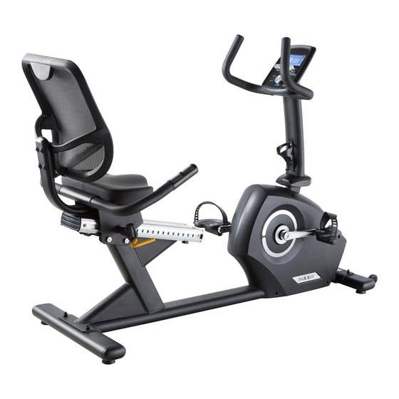
Page 4: Overview Of The Device
Overview of the Device Cockpit Handlebars Pulse sensors Handlebar Shaft Back Rest Pedal Mains Adapter Connection Stand with Transport Rollers Stand Lever for Seat Adjustment Scope of Delivery Item Description Item Description Base Frame Seat Stand, front Back Rest Stand, rear Cockpit Handlebar Shaft Handlebar Covers... - Page 5 Fixing Materials Item Description Item Description Hex Bolt, 3/8" Washer, M8 Hex Bolt, M8x25 Cap Nut, 3/8" Hex Socket Screw, M8x12 Hex Socket Screw, M8x25 Hex Screw with Flange Pan Head Screw, 1/4"x2" Washer, 3/8" Self-Tapping Screw, M5x16 Washer, 1/4" Tools Included in Delivery Item Description...
- Page 6 Assembly Carefully unpack all parts of the delivery. Two people are required because some parts of your training device are bulky and heavy. Before starting the assembly, check the completeness of the fixing materials (screws, nuts, etc.) and the components against the parts and fixing material lists on the previous pages of this manual. Carefully carry out the installation, as damage or defects that have arisen due to assembly errors are not covered by the warranty under any circumstances.
- Page 7 Assembly Step 3: Assembling the Handlebar Shaft Connect the connectors of the three cables coming out of the bottom of the handlebar shaft (D) to the connec- tors of the three cables protruding from the base frame (A). CAUTION: From the three cables, two have identical connectors. As these are the hand pulse sensor cables, it is not pos- sible to mix the cables up.
-
Page 8: Step 5: Assembling The Handlebars
Assembly Step 5: Assembling the Handlebars Pass the hand pulse sensor cable and the cockpit cable coming out of the top of the handlebar (D), from below and up through the opening in the handlebars (E). Now pull the cable end just far enough out so that you can connect them to the cockpit. -
Page 9: Step 8: Assembling The Pedals
Assembly Step 8: Assembling the Pedals Insert the right pedal (F) into the right pedal arm sock- et and tighten it clockwise. Insert the left pedal (F) into the left pedal arm socket and tighten it anti-clockwise. Step 9: Assembling the Back Rest Fix the back rest (J) using four pan head screws ¼”x 2”... -
Page 10: Step 11: Assembling The Seat
Assembly Step 11: Assembling the Seat Fix the seat (I) onto the base plate of the handles (H) using four hexagon socket screws M8x25 (12). Then connect the two hand pulse cables protruding out of the handles (H) with the connector on the spiral cable – it is not possible to connect these wrongly. -
Page 11: Seat Adjustment
Seat Adjustment Horizontal Adjustment You can adjust your training device horizontally to your individual requirements. Loosen the seat lock by pulling upwards on the hand lever located to the right under your seat. Press with your feet against the pedals to push the seat backwards or pull it forwards. -
Page 12: Care, Cleaning & Maintenance
Transport, Location & Storage Transport In order to transport your training device simply and safely, the front stand is equipped with transport rollers. To move the exerciser, stand in front of the handlebars and grab them with both hands. Pull the training device gently towards you and lower the handlebars until the rear stand no longer has contact with the ground and the main weight of the exerciser is resting on the transport rollers. -
Page 13: Mains Connection
Mains Connection Mains Cable Insert the connector of the power cable supplied into the socket located on the rear front of the main housing. Then connect the mains cable to a power socket. NOTE: The USB connection on the cockpit of this training device is not for the connection of the mains adapter!! This USB connector is only for the connection of a USB charging cable (not included in delivery) for smartphones, Tablet PC’s, Ebooks etc. - Page 14 Cockpit USB port with charging function LCD display Storage compartment for Smartphone, Tablet PC Control knob Recovery pulse measurement RESET key RECOVERY RESET BODYFAT START/STOP Body fat analysis START / STOP key MODE The cockpit constantly shows the current training values. TIME Specification of the training time.
- Page 15 Cockpit Keypad START/STOP Key START Function: – Start the selected training program or training profile – Activate the QUICK START function PAUSE Function: If the START / STOP key is pressed during training, the display of training values stops, and the pause mode is activated. This allows an interruption of training. To end the pause, press the START / STOP key again.
-
Page 16: Quick Start
Cockpit Quick-Start Turn on the training device and press the START / STOP key. The training time will start to run, and you can start training. At any time during training, you can adjust the resistance level from 1 to 16 by turning the control knob clockwise / anti-clockwise. - Page 17 Cockpit Training Profiles P1 – P12 In this type of training, the user can choose from twelve pre-programmed training profiles. The profile is not changeable; however, the user has the option of adjusting the intensity of the respective profile according to their current state of fitness.
- Page 18 Cockpit Free Training Profile (USER) Here you can create a training profile per user profile yourself and save it permanently. Step 1: Selecting a Program Turn on the exerciser. The upper part of the display flashes “M”. Select the program “U” by turning the control knob clockwise / anti-clockwise and confirm your selection by pressing it.
- Page 19 Cockpit Step 4: Setting the Training Time The value in the “TIME” window flashes. Enter the training time by turning the control knob clockwise / an- ti-clockwise. You can set the exercise time from 1:00 to 99:00 minutes in 1-minute increments. Step 5: Training Start Press the START / STOP key to start exercising.
- Page 20 Cockpit Recovery Heart Rate (RECOVERY) The recovery test measures how quickly you recover, i.e. how quickly and by how much your heart rate de- creases after training. After completing a workout, or after stopping the workout by pressing the Stop key, press the RECOVERY key and immediately place your hands on the hand pulse sensors.
- Page 21 After successfully pairing the App with your training device, you can continue training by clicking on the arrow in the top right corner of the display. Please note that the MAXXUS Group GmbH & Co. KG is not the manufacturer of the iC + Training App and therefore are not responsible for their content or features.
-
Page 22: Pulse & Heart Rate
Pulse & Heart Rate 100% of maximum heart rate of maximum heart rate of maximum heart rate of maximum heart rate Calculating your personal heart rate when training Calculate your personal heart rate when training as follows: 220 - Age = maximum heart rate This value represents your maximum heart rate and serves as a basis from which to calculate your personal training heart rate. - Page 23 Heart Rate Measurement using a Chest Belt Many MAXXUS® training devices are already fitted with a receiver as standard. Using a chest belt (we recommend the exclusive use of an uncoded POLAR® chest strap) allows you to wire- lessly measure heart rate. The chest belt is as accessories available.
-
Page 24: Training Recommendations
Training Recommendations Preparation Before Training Before you start training make sure that not only your training device is in perfect condition, your body must also be prepared for training. Therefore, if you have not done any endurance training for some time, you should con- sult your GP and undergo a fitness check-up. - Page 25 Training Recommendations Hydration Adequate hydration is essential before and during exercise. During a training session of 30 minutes it is possible to lose up to 1 litre of liquid. To compensate for this fluid loss apple spritzer mixed in the ratio of one-third apple juice to two-thirds mineral water is ideal since it contains electrolytes and minerals to replace those that the body loses through sweat.
-
Page 26: Technical Details
Technical Details Cockpit Display of: − Time − Pulse Rate (when using the hand sensors) − Speed − Watts − Distance − Heart rate (when using an optional chest belt) − Revolutions per minute − Resistance level − Calorie consumption Technical details: Brake system: Motor-controlled permanent magnetic brake system... -
Page 27: Recommended Accessories
All these extremely high-quality components ensure that all func- tional noises are very much reduced. Your MAXXUS® training device is one of the quietest products available in the fitness market. -
Page 28: Exploded Drawing
Exploded Drawing... -
Page 29: Spare Parts List
Spare Parts List Description Description Welded,Main Frame Lock Pin Welded,Upright Tube M8 Locknut Welded,Slide Assembly M8 Hex Screw Welded,Hand Bar Pulley Shaft Welded,Shaft Pulley M6 Socket Screw Welded,Pressure Assembly M6 Hex Screw Welded,Back Tube Ø1/4" Washer Stabilizer-Behind M6 Screw Welded,Stabilizer-Front M8 Hex Screw Welded,Seat Assembly Ø8 Washer... -
Page 30: Terms And Conditions Of Warranty
The warranty period for your training device starts on the date of purchase and applies solely to products which were purchased directly from the MAXXUS Group GmbH & Co KG or one of the MAXXUS Group GmbH & Co KG direct and authorised distribution partners. -
Page 31: Service Contract
I accept the General Terms and Conditions of MAXXUS® Group GmbH & Co. KG. I hereby instruct the company MAXXUS® Group GmbH & Co. KG to repair the above defects. In Warranty cases I will not be charged for the cost. The costs for repairs which are excluded from liability for defects in quality will be charged to me and must be settled my signature. - Page 32 Maxxus Group GmbH & Co. KG Nordring 80 D-64521 Gross-Gerau Germany E-Mail: info@maxxus.de www.maxxus.com...
Need help?
Do you have a question about the 4.2 R and is the answer not in the manual?
Questions and answers