Table of Contents
Advertisement
Quick Links
Advertisement
Table of Contents

Related Manuals for Maxxus SpeedBike S1


Summary of Contents for Maxxus SpeedBike S1
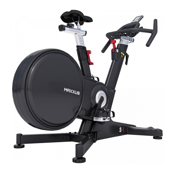
- Page 1 SpeedBike...
- Page 2 This publication may not be reproduced, stored in a retrieval system, or transmitted in whole or in part, in any form or by any means, electronic, mechanical, photocopying, recording, or otherwise without the prior written permission of Maxxus Group GmbH & Co. KG.
-
Page 3: Safety Instructions
Safety Instructions Before you start exercising, be sure to read the entire user guide, especially the safety information, the maintenance & cleaning in- formation and the training information. Take care too that everyone who uses this training device is also familiar with this information and observes it. -
Page 4: Overall View Of The Device
Overall View of the Device Description Description Cockpit Stand with transport rollers Handle to adjust the position of the handlebars Pedal Handlebars Stand, rear Handlebar Tube Lever to adjust the height of the seat Emergency Stop Lever Seat tube Bottle Holder Knob to adjust the seat backwards and forwards. -
Page 5: Scope Of Delivery
Scope of Delivery 41L/R Description Qty. Description Qty. Base Frame Cover stand, front Handlebars Knob Stand, rear Holder Stand, front Cockpit Pedal L (left)/ Pedal R (right) Cockpit Bracket Seat Stand feet... - Page 6 Scope of Delivery Description Qty. Description Qty. Washer Ø6xØ16x1,6T Allen screw M4x12 Washer Ø9xØ161,6T Washer Ø4,3xØ12x0,8T Allen screw M8x12 Allen key 6mm Allen screw M6x20 Allen key 5mm Allen screw M6x12 Allen key 4mm Allen screw M10x30 Spanner 13 / 15 Nut M10 Phillips screwdriver - combi Allen screw M6x15...
- Page 7 Assembly Step 1: Assembly of the Stand Feet Screw a nut M10 (110) on each of the four stand feet (48) Now insert a stand foot to the underside of each of the rear stands (5) and the other two stand feet to the under- side of the front stand (6).
- Page 8 Assembly Step 3: Assembly of the Rear Stands Insert the two rear stands (5) into the mounts on the base frame and fix them from above using three washers Ø9xØ161,6T (94) and three Allen screws M8x12 (97) on each stand. Step 4: Assembly of the Seat Place the seat (47) onto the seat stem and fix it on using the spanner (115).
- Page 9 Assembly Step 5: Assembly of the Handlebars Step 5.1: Insert the knob (59) with a washer Ø6xØ16x1.6T (81) from above into the handlebar shaft Step 5.2: Loosen knob (59) and slide the carriage of the horizontal handlebar to adjustment backwards towards the seat (Fig.
- Page 10 Assembly Step 5.3: Slot on and fix the handlebars onto the horizontal handlebar adjustment slide using four Allen screws M6x15 (103). Now attach the holder (73) and the cockpit (118) to the handlebars. To do this use two Allen screws M6x15 (111) and two washers (81).
-
Page 11: Levelling The Device
Assembly Step 7: Assembly of the Pedals Insert the pedal marked with an “R” (41R) into the thread of the right pedal arm and attach it by tightening it clockwise (standard right-hand thread). Now insert the pedal marked with an “L” (41L) into the thread of the left pedal arm and attach it by tightening it in an anti-clockwise direction (left-hand thread). -
Page 12: Maintenance And Care
Transport In order to transport your training device simply and safely, the front stand is equipped with transport rollers. To move the exerciser, stand in front of the handlebars and grab them with both hands. Pull the training device gently towards you and lower the handlebars until the rear stand no longer has contact with the ground and the main weight of the exerciser is resting on the transport rollers. -
Page 13: Vertical Seat Adjustment
Adjusting the Sitting Position Vertical Seat Adjustment You can change the position of the seat vertically, i.e. adjust the height. With this you can find the optimal distance to the pedals. Loosen the lever on the seat tube by pulling it upwards. Adjust the seat to the desired height and fix the seat tube in position again by pushing down the lever. - Page 14 Adjusting the Sitting Position Vertical Handlebar Adjustment It is possible to change the vertical position, or height of the handlebars. To do this loosen the lever on the front of the handlebar shaft. Adjust the handlebars to the desired position and then tighten the lever again. CAUTION: The maximum handlebar height adjustment is marked on the handlebar stem with “STOP”...
-
Page 15: Seat Position
Adjusting the Sitting Position Seat Position Stand next to the bike and adjust the seat to a height a width of two-fingers below your hip joint. Then sit on the seat and put your feet onto the pedals. Your knees should still be bent at a small angle when the pedal is at its lowest point. Never train with your knees completely straight at this pedal position (Fig. -
Page 16: Adjusting The Braking Resistance
Adjusting the Braking Resistance The braking resistance may be adjusted using the adjustment lever. The further you push the lever down, the great- er the braking resistance will be. The further upwards you push the lever, the lighter the braking resistance will be. Note: You should never pedal backwards under resistance load as the screw connection of the pedals to the pedal arms can loosen and come undone. -
Page 17: Displayed Values
The energy consumption displayed is an approximation and not an exact value. ** Note on heart rate measurement An optionally available heart rate transmitter belt is required for this. MAXXUS recommends using a POLAR T34. -
Page 18: Changing The Batteries
Cockpit Before you start your first training session After assembling your Speedbike and before starting with your first training session, please check if the cockpit is receiving the signal correctly. Insert two type AAA 1.5-volt batteries into the cockpit. Pedal for at least 2 minutes using the pedals. During this time, make sure that the cockpit has a perfect connection to the sensor. -
Page 19: Recovery Measurement
Cockpit Recovery Measurement If the user is wearing an optionally available chest belt for heart rate measurement, the cockpit will show their current heart rate. Once training has ended, press the RECOVERY key to activate the recovery measurement function. A one-minute countdown will be shown on the display along with the current heart rate. After one min- ute, the recovery pulse measurement will be shown on the basis of school grades. -
Page 20: Pulse & Heart Rate
Pulse & Heart Rate 100% of maximum heart rate of maximum heart rate of maximum heart rate of maximum heart rate Calculating your personal heart rate when training Calculate your personal heart rate when training as follows: 220 - Age = maximum heart rate This value represents your maximum heart rate and serves as a basis from which to calculate your personal training heart rate. - Page 21 Using a chest belt (we recommend the exclusive use of an uncoded POLAR® chest belt) allows you to wireless- ly measure heart rate. The chest belt is available online as an accessory from www.maxxus.com. This optimal, ECG-accurate type of measurement takes the heart rate by means of a transmitter chest belt directly from the skin.
-
Page 22: Training Recommendations
Training Recommendations Preparation Before Training Before you start training make sure that not only your training device is in perfect condition, your body must also be prepared for training. Therefore, if you have not done any endurance training for some time, you should con- sult your GP and undergo a fitness check-up. - Page 23 Training Recommendations Hydration Adequate hydration is essential before and during exercise. During a training session of 30 minutes it is possible to lose up to 1 litre of liquid. To compensate for this fluid loss apple spritzer mixed in the ratio of one-third apple juice to two-thirds mineral water is ideal since it contains electrolytes and minerals to replace those that the body loses through sweat.
-
Page 24: Technical Details
Technical Details Cockpit: Displays: − Time − Calorie Consumption − Speed − Heart Rate − Distance (when using an optional chest belt) − Wheel Revolutions per Minute Technical Details: Braking System: manual magnetic brake system Drive Type: two-stage longitudinal ribbed belt Flywheel: approx. -
Page 25: Recommended Accessories
My training device makes noises during training – is this normal? Your MAXXUS® training device is equipped with high-quality ball-bearings and a grooved belt. In addition, it also has a high-quality magnetic braking system which is completely wear and friction free. All these extremely high-quality components ensure that all functional noises are very much reduced. -
Page 26: Exploded Drawing
Exploded Drawing... -
Page 27: Spare Parts List
Spare Parts List Description Specifications Qty. Main frame Upright extension tube Seat tube Handle Rear floor tube Front floor tube Cross welding Seat tube sliding set 9L/9R Crank shaft L/R Idler wheel shaft Brake handle Seat handle 13L/13R Seat gear seat L/R Seat tube outer bushing Belt pulley shaft Ø25*159.6L... - Page 28 Spare Parts List Description Specifications Qty. shaft 6003ZZ shaft 6205ZZ shaft 6203ZZ PK belt PK-1345-J5, black Seat Adjusting foot pad Chain cover L Chain cover R Upright front cover L Upright front cover R Front floor tube cover Crank shaft cover 123.5*16 Brake cover L Brake cover R...
- Page 29 Spare Parts List Description Specifications Qty. Screw M8*20 10.9grade Screw M4*12 10.9grade Screw M5*15 10.9grade Screw M5*40 10.9grade Screw M6*10 10.9grade Screw M6*15 10.9grade Screw M6*20 10.9grade Screw M6*25 10.9grade Washer Ø9*Ø16*t1.6 Screw M5*8 10.9grade Screw M6*40 10.9grade Screw M8*12 10.9grade Screw M8*75 10.9grade Screw...
-
Page 30: Terms And Conditions Of Warranty
The warranty period for your training device starts on the date of purchase and applies solely to products which were purchased directly from the MAXXUS Group GmbH & Co KG or one of the MAXXUS Group GmbH & Co KG direct and authorised distribution partners. -
Page 31: Service Contract
I accept the General Terms and Conditions of MAXXUS® Group GmbH & Co. KG. I hereby instruct the company MAXXUS® Group GmbH & Co. KG to repair the above defects. In Warranty cases I will not be charged for the cost. The costs for repairs which are excluded from liability for defects in quality will be charged to me and must be settled immediately. - Page 32 Maxxus Group GmbH & Co. KG Nordring 80 D-64521 Groß-Gerau Germany E-Mail: info@maxxus.de www.maxxus.com...
Need help?
Do you have a question about the SpeedBike S1 and is the answer not in the manual?
Questions and answers